Showing posts with label Contiki. Show all posts

Tuesday, April 24, 2018

How to setup Mosquitto on Raspberry Pi and make Contiki/Contiki-NG cc26xx-web-demo do mqtt publish to it.

The following steps show you how to setup Mosquitto on Raspberry Pi and make Contiki/Contiki-NG cc26xx-web-demo do mqtt publish to it.

1. Login to Raspberry Pi and do the following steps to install Mosquitto.
  • 1.1 Run "apt-get update" and "apt-get install mosquitto" to install Mosquitto server.
  • 2.2 Run "apt-get install mosquitto-clients" to install mosquitto_sub and mosquitto_pub.
2. Follow steps in How to configure 6lbr to make it can do ping6 to a CC26xx/CC13xx node from Raspberry Pi running 6lbr to setup 6lbr in bridge router mode.

3. Do "ifconfig" to get br0 IPv6 address. In my case, it's "bbbb::e786:9d85:9446:709".


4. Go to cc26xx-web-demo MQTT/IBM Cloud Config page and set "bbbb::e786:9d85:9446:709" as broker IP.


5. Open another ssh login to Raspberry pi and run "mosquitto_sub -h bbbb::e786:9d85:9446:709 -t iot-2/evt/status/fmt/json" to subscribe to ccx6xx-web-demo publish topic. You should be it receives cc26xx-web-demo published MQTT messages.


p.s. You can also use "mosquitto_pub -h bbbb::e786:9d85:9446:709 -p 1883 -t iot-2/evt/status/fmt/json -m "hello"" to test MQTT message publish from Raspberry Pi terminal.

6. The following steps show you how to toggle red led on LAUNCHXL-CC1310 or LAUNCHXL-CC2560 running cc26xx-web-demo.
  •  Use "test" as Org ID instead of "quickstart" and "123456" as Auth Token instead of empty.
  • Click "Submit" to make cc26xx-web-demo to reconnect to mqtt server.
  • Start a ssh login to raspberry pi. Use "mosquitto_pub -h bbbb::e786:9d85:9446:709 -m "1" -t iot-2/cmd/leds/fmt/json" to turn on red led, or "mosquitto_pub -h bbbb::e786:9d85:9446:709 -m "0" -t iot-2/cmd/leds/fmt/json" to turn off red led.


Tuesday, April 10, 2018

Connect IBM quickstart of Contik cc26xx-web-demo to node-red for data processing.

The following steps show you how to connect IBM quickstart of Contik cc26xx-web-demo to node-red for data processing.

1.Login to IBM Bluemix and switch to Dashboard. Click "Create resource" button to create node-red.

2. Add node-red to filter. Find "Node-RED starter" and click it to create node-red application,


3.Give an App name and click "Create" button.


4. Wait the service to be started. It will take a while.

5. After service starts, click "Visit App URL" to access to node-red flow editor.

6. You will need to follow the steps in the wizard to setup node-red editor account when you create it first time.
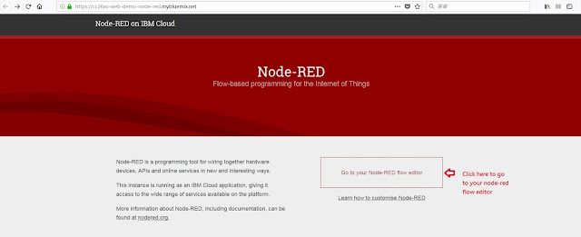
7.Then, click on "Go to your Node-RED flow editor" to access to node-red URL.


8. This is Node-RED flow editor.

9. Switch to IBM quickstart and click on "IMPORT FLOW"

10. Copy the data.

11. Click hamburger icon -> import -> Clipboard to import data from IBM quickstart.

12. Paste the data and click "import"

13. IBM quickstart of mapped device status are imported. Click "Deploy" button to deploy it.

14. You can see data starts streaming on debug window.

15. You can construct your data flow to storage like mangoDB or process them.

Wednesday, November 29, 2017

Using Contiki UDP client to send ON/OFF command to remote UDP server to toggle LED on CC13xx/CC26xx.

The following steps show you how to revise Contiki UDP client/server examples to allow you send UART ON/OFF command to UDP client, UDP client sends ON/OFF command over the air to UDP server, and UDP server toggles red LED. The following tests are done using two LAUNCHXL-CC1310.

1. Revise the following red lines in udp-client.c
...
#include "net/ip/uip-udp-packet.h"
#include "sys/ctimer.h"
#include "dev/leds.h"
#ifdef WITH_COMPOWER
#include "powertrace.h"
#endif
#include
#include

...
static struct uip_udp_conn *client_conn;
static uip_ipaddr_t server_ipaddr;

char cmd[16];

/*---------------------------------------------------------------------------*/
PROCESS(udp_client_process, "UDP client process");
AUTOSTART_PROCESSES(&udp_client_process);
/*---------------------------------------------------------------------------*/
static int seq_id;
static int reply;
...

/*---------------------------------------------------------------------------*/
static void
send_packet(void *ptr)
{
  char buf[MAX_PAYLOAD_LEN];

#ifdef SERVER_REPLY
  uint8_t num_used = 0;
  uip_ds6_nbr_t *nbr;

  nbr = nbr_table_head(ds6_neighbors);
  while(nbr != NULL) {
    nbr = nbr_table_next(ds6_neighbors, nbr);
    num_used++;
  }

  if(seq_id > 0) {
    ANNOTATE("#A r=%d/%d,color=%s,n=%d %d\n", reply, seq_id,
             reply == seq_id ? "GREEN" : "RED", uip_ds6_route_num_routes(), num_used);
  }
#endif /* SERVER_REPLY */

  seq_id++;
  PRINTF("CMD:%s send to %d SEQ_ID:%d\n",cmd,
         server_ipaddr.u8[sizeof(server_ipaddr.u8) - 1], seq_id);
  sprintf(buf, "%s from the client SEQ_ID:%d ",cmd, seq_id);
  uip_udp_packet_sendto(client_conn, buf, strlen(buf),
                        &server_ipaddr, UIP_HTONS(UDP_SERVER_PORT));
}
/*---------------------------------------------------------------------------*/
...

/*---------------------------------------------------------------------------*/
PROCESS_THREAD(udp_client_process, ev, data)
{
  static struct etimer periodic;
  static struct ctimer backoff_timer;
#if WITH_COMPOWER
  static int print = 0;
#endif

  PROCESS_BEGIN();

  PROCESS_PAUSE();

  cc26xx_uart_set_input(serial_line_input_byte);
 
  set_global_address();

  PRINTF("UDP client process started nbr:%d routes:%d\n",
         NBR_TABLE_CONF_MAX_NEIGHBORS, UIP_CONF_MAX_ROUTES);

  print_local_addresses();

  /* new connection with remote host */
  client_conn = udp_new(NULL, UIP_HTONS(UDP_SERVER_PORT), NULL);
  if(client_conn == NULL) {
    PRINTF("No UDP connection available, exiting the process!\n");
    PROCESS_EXIT();
  }
  udp_bind(client_conn, UIP_HTONS(UDP_CLIENT_PORT));

  PRINTF("Created a connection with the server ");
  PRINT6ADDR(&client_conn->ripaddr);
  PRINTF(" local/remote port %u/%u\n",
    UIP_HTONS(client_conn->lport), UIP_HTONS(client_conn->rport));

#if WITH_COMPOWER
  powertrace_sniff(POWERTRACE_ON);
#endif

  etimer_set(&periodic, SEND_INTERVAL);
  while(1) {
    PROCESS_YIELD();
    if(ev == tcpip_event) {
      tcpip_handler();
    }

    if(ev == serial_line_event_message && data != NULL) {
      printf("command received:%s\n",(char *)data);
      
if(strcmp(data,"ON")==0){
         for(int i=0; i < 16 ; i=i+1) cmd[i]=0x0;
         cmd[0]=0x4F;
         cmd[1]=0x4E;
         leds_on(LEDS_RED);
      }else if(strcmp(data,"OFF")==0){
 
         for(int i=0; i < 16 ; i=i+1) cmd[i]=0x0;        
         cmd[0]=0x4F;
         cmd[1]=0x46;
         cmd[2]=0x46;
         leds_off(LEDS_RED);
      }
      send_packet(NULL); 

    }

    if(etimer_expired(&periodic)) {
      etimer_reset(&periodic);
      ctimer_set(&backoff_timer, SEND_TIME, send_packet, NULL);

#if WITH_COMPOWER
      if (print == 0) {
    powertrace_print("#P");
      }
      if (++print == 3) {
    print = 0;
      }
#endif

    }
  }

  PROCESS_END();
}
/*---------------------------------------------------------------------------*/

2. Build udp-client.bin by "make TARGET=srf06-cc26xx BOARD=launchpad/cc1310 udp-client.bin" and download udp-client.bin to one LAUNCHXL-CC1310.


3. Revise the following red lines in udp-server.c
...
#define DEBUG DEBUG_PRINT
#include "net/ip/uip-debug.h"
#include "dev/leds.h"

#define UIP_IP_BUF   ((struct uip_ip_hdr *)&uip_buf[UIP_LLH_LEN])
...
/*---------------------------------------------------------------------------*/
static void
tcpip_handler(void)
{
  char *appdata;

  if(uip_newdata()) {
    appdata = (char *)uip_appdata;
    appdata[uip_datalen()] = 0;
    PRINTF("DATA recv '%s' from ", appdata);
    if(appdata[0]==0x4F && appdata[1]==0x4E ){
        leds_on(LEDS_RED);
    }
    if(appdata[0]==0x4F && appdata[1]==0x46 && appdata[2]==0x46){
        leds_off(LEDS_RED);
    }
   
    PRINTF("%d",
           UIP_IP_BUF->srcipaddr.u8[sizeof(UIP_IP_BUF->srcipaddr.u8) - 1]);
    PRINTF("\n");
#if SERVER_REPLY
    PRINTF("DATA sending reply\n");
    uip_ipaddr_copy(&server_conn->ripaddr, &UIP_IP_BUF->srcipaddr);
    uip_udp_packet_send(server_conn, "Reply", sizeof("Reply"));
    uip_create_unspecified(&server_conn->ripaddr);
#endif
  }
}
/*---------------------------------------------------------------------------*/
...


4. Build udp-server.bin by "make TARGET=srf06-cc26xx BOARD=launchpad/cc1310 udp-server.bin" and download udp-server.bin to another LAUNCHXL-CC1310.

5. Start UDP server on one LAUNCHXL-CC1310 running udp-server.bin and start UDP client on another LAUNCHXL-CC1310 running udp-client.bin.


6. You can enter "ON" and "CTRL+Enter" to send ON command with end character "0x0A" to COM port of LAUNCHXL-CC1310 running UDP client and you will see red led is turned ON on another LAUNCHXL-CC1310 running UDP server.

7. You can enter "OFF" and "CTRL+Enter" to send OFF command with end character "0x0A" to COM port of LAUNCHXL-CC1310 running UDP client and you will see red led is turned OFF on another LAUNCHXL-CC1310 running UDP server.

Thursday, October 19, 2017

Using CC13xx/CC26xx running Contiki OS to toggle LED from UART.

The following example shows how to using CC13xx/CC26xx running Contiki OS to toggle LED from UART.

1. Replace the following code into hell-world.c

#include "contiki.h"
#include "dev/cc26xx-uart.h"
#include "dev/serial-line.h"
#include "dev/leds.h"

#include < stdio.h >/* For printf() */
#include  < string.h >


 PROCESS(test_serial, "Serial line test process");
 AUTOSTART_PROCESSES(&test_serial);

 PROCESS_THREAD(test_serial, ev, data)
 {
   PROCESS_BEGIN();
   cc26xx_uart_set_input(serial_line_input_byte);
  
   printf("Hello, world Serial line test\n");

   for(;;) {
     PROCESS_YIELD();
     if(ev == serial_line_event_message) {
       printf("received line: %s\n", (char *)data);
       if(strcmp(data,"ON")==0)
           leds_on(LEDS_GREEN);
       else if(strcmp(data,"OFF")==0)
           leds_off(LEDS_GREEN);
     }
   }
   PROCESS_END();
 }


2. Build hello-world.bin for LAUNCHXL-CC1310 using  "make TARGET=srf06-cc26xx BOARD=launchpad/cc1310 hello-world.bin"

3. Download hello-world.bin to LAUNCHXL-CC1310 using Flash Programmer 2.

4. Start a terminal tool like teraterm to connect to LAUNCHXL-CC1310 application virtual COM port..

5. Enter "ON" and "CTRL+Enter" to send ON command with end character "0x0A" to LAUNCHXL-CC1310 and you will see green led is turned on

6. Enter "OFF" and "CTRL+Enter" to send OFF command with end character "0x0A" to LAUNCHXL-CC1310 and you will see green led is turned on

Friday, March 3, 2017

How to run Contiki udp-server/udp-client on LAUNCHXL-CC2650.

The following steps show you how to run Contiki udp-server/udp-client on LAUNCHXL-CC2650.

1. Do "make TARGET=srf06-cc26xx BOARD=launchpad/cc2650 udp-server.bin" under /contiki/examples/ipv6/rpl-udp to build udp-server.bin and download it to one of LAUNCHXL-CC2650 using Flash Programmer 2.


2. Do "make TARGET=srf06-cc26xx BOARD=launchpad/cc2650 udp-client.bin" under /contiki/examples/ipv6/rpl-udp to build udp-client.bin and download it to another LAUNCHXL-CC2650 using Flash Programmer 2.

3. Start 6lbr on Raspberry Pi or BeagleBone and power on udp-server and udp-client on two different LAUNCHXL-CC2650. You will see two LAUNCHXL-CC2650 show on sensor list of 6lbr web page.


4. On UART output of two LAUNCHXL-CC2650, you can see udp-client sends Hello messages to udp-server.

Wednesday, February 15, 2017

How to do settings to allow access 6lbr from Internet

The following steps show you how to do settings to allow access 6lbr from Internet. Let's say we have a Internet router (mine is Asus RT-N12HP_B1) and the LAN address is 192.168.1.xxx.

1. Access to 6lbr web page (http://[bbbb::100]) inside LAN and go to configuration page of 6lbr. Select IP64: on, DHCP: off, input a IPv4 address 192.168.1.2 (this might be different if you don't use 192.168.1.xxx as LAN address on your Internet router and you can use other IP such as 192.168.1.123 if you like it more.), and set Gateway as 192.168.1.1 (this might be also different if you don't use 192.168.1.xxx as LAN address on your Internet router). Then, press "Submit" to restart 6lbr.


2.  After restarting, you can check IP64 Address is 192.168.1.2 now on 6lbr Info page.


3. Next, let's check settings on Internet router (mine is Asus RT-N12HP_B1). We can see the external IP of this router is 220.136.172.175.


4.I add a port forwarding rule (assign http service port to 6lbr IPv4 address 192.168.1.2) to this Internet router and restart it.


5. Now, I can access 6lbr from another desktop from elsewhere on Internet by http://220.136.172.175


Thursday, February 9, 2017

How to add a COAP resource to read ADC input from DIO23 in Contiki cc26xx-web-demo on CC2650 LaunchPad.

To add a COAP resource to read ADC input from DIO23 in Contiki cc26xx-web-demo on CC2650 LaunchPad, you have to add the following code with "+" into your cc26xx-web-demo.c, cc26xx-web-demo.h, coap-server.c, and res-sensors.c.

1. /examples/cc26xx/cc26xx-web-demo/cc26xx-web-demo.c
@@ -55,9 +55,15 @@
 #include
 #include
 #include
+
+#include "ti-lib.h"
+#include "driverlib/aux_adc.h"
+#include "driverlib/aux_wuc.h"
+

 /*---------------------------------------------------------------------------*/
 PROCESS_NAME(cetic_6lbr_client_process);
 PROCESS(cc26xx_web_demo_process, "CC26XX Web Demo");
+PROCESS(adc_process, "ADC process");
 /*---------------------------------------------------------------------------*/
 /*
  * Update sensor readings in a staggered fashion every SENSOR_READING_PERIOD
@@ -84,6 +90,9 @@ static struct uip_icmp6_echo_reply_notification echo_reply_notification;
 static struct etimer echo_request_timer;
 int def_rt_rssi = 0;
 #endif
+
+uint16_t singleSample;
+

 /*---------------------------------------------------------------------------*/
 process_event_t cc26xx_web_demo_publish_event;
 process_event_t cc26xx_web_demo_config_loaded_event;
@@ -110,6 +119,9 @@ DEMO_SENSOR(batmon_temp, CC26XX_WEB_DEMO_SENSOR_BATMON_TEMP,
 DEMO_SENSOR(batmon_volt, CC26XX_WEB_DEMO_SENSOR_BATMON_VOLT,
             "Battery Volt", "battery-volt", "batmon_volt",
             CC26XX_WEB_DEMO_UNIT_VOLT);
+DEMO_SENSOR(adc_dio23, CC26XX_WEB_DEMO_SENSOR_ADC_DIO23,
+            "ADC DIO23", "adc-dio23", "adc_dio23",
+            CC26XX_WEB_DEMO_UNIT_VOLT);

 /* Sensortag sensors */
 #if BOARD_SENSORTAG
@@ -464,6 +476,14 @@ get_batmon_reading(void *data)
     }
   }

+  if(adc_dio23_reading.publish) {
+    if(1) {
+      buf = adc_dio23_reading.converted;
+      memset(buf, 0, CC26XX_WEB_DEMO_CONVERTED_LEN);
+      snprintf(buf, CC26XX_WEB_DEMO_CONVERTED_LEN, "%d", singleSample);
+    }
+  }
+

   ctimer_set(&batmon_timer, next, get_batmon_reading, NULL);
 }
 /*---------------------------------------------------------------------------*/
@@ -825,6 +845,7 @@ init_sensors(void)

   list_add(sensor_list, &batmon_temp_reading);
   list_add(sensor_list, &batmon_volt_reading);
+  list_add(sensor_list, &adc_dio23_reading);
   SENSORS_ACTIVATE(batmon_sensor);

 #if BOARD_SENSORTAG
@@ -864,6 +885,7 @@ PROCESS_THREAD(cc26xx_web_demo_process, ev, data)

   /* Start all other (enabled) processes first */
   process_start(&httpd_simple_process, NULL);
+  process_start(&adc_process, NULL);
 #if CC26XX_WEB_DEMO_COAP_SERVER
   process_start(&coap_server_process, NULL);
 #endif
@@ -966,6 +988,56 @@ PROCESS_THREAD(cc26xx_web_demo_process, ev, data)

   PROCESS_END();
 }
+
+PROCESS_THREAD(adc_process, ev, data)
+{
+  PROCESS_BEGIN();
+  static struct etimer et_adc;
+  while(1)
+  {
+         etimer_set(&et_adc, CLOCK_SECOND*5);
+         PROCESS_WAIT_EVENT();
+         if(etimer_expired(&et_adc)) {
+               //intialisation of ADC
+               ti_lib_aon_wuc_aux_wakeup_event(AONWUC_AUX_WAKEUP);
+               while(!(ti_lib_aon_wuc_power_status_get() & AONWUC_AUX_POWER_ON))
+               { }
+
+               // Enable clock for ADC digital and analog interface (not currently enabled in driver)
+               // Enable clocks
+               ti_lib_aux_wuc_clock_enable(AUX_WUC_ADI_CLOCK | AUX_WUC_ANAIF_CLOCK | AUX_WUC_SMPH_CLOCK);
+               while(ti_lib_aux_wuc_clock_status(AUX_WUC_ADI_CLOCK | AUX_WUC_ANAIF_CLOCK | AUX_WUC_SMPH_CLOCK) != AUX_WUC_CLOCK_READY)
+               { }
+               //printf("clock selected\r\n");
+
+               // Connect AUX IO7 (DIO23, but also DP2 on XDS110) as analog input.
+               AUXADCSelectInput(ADC_COMPB_IN_AUXIO7);
+               //printf("input selected\r\n");
+
+               // Set up ADC range
+               // AUXADC_REF_FIXED = nominally 4.3 V
+               AUXADCEnableSync(AUXADC_REF_FIXED,  AUXADC_SAMPLE_TIME_2P7_US, AUXADC_TRIGGER_MANUAL);
+               //printf("init adc --- OK\r\n");
+
+               //Trigger ADC converting
+               AUXADCGenManualTrigger();
+               //printf("trigger --- OK\r\n");
+
+               //reading adc value
+               singleSample = AUXADCReadFifo();
+
+               printf("%d mv on ADC\r\n",singleSample);
+
+               //shut the adc down
+               AUXADCDisable();
+               //printf("disable --- OK\r\n");
+               get_batmon_reading(NULL);
+
+               etimer_reset(&et_adc);
+               }
+  }
+  PROCESS_END();
+}


2./examples/cc26xx/cc26xx-web-demo/cc26xx-web-demo.h
@@ -146,6 +146,7 @@
 #define CC26XX_WEB_DEMO_SENSOR_MPU_GYRO_X    12
 #define CC26XX_WEB_DEMO_SENSOR_MPU_GYRO_Y    13
 #define CC26XX_WEB_DEMO_SENSOR_MPU_GYRO_Z    14
+#define CC26XX_WEB_DEMO_SENSOR_ADC_DIO23     15
 /*---------------------------------------------------------------------------*/
 extern process_event_t cc26xx_web_demo_publish_event;
 extern process_event_t cc26xx_web_demo_config_loaded_event;

3. /examples/cc26xx/cc26xx-web-demo/coap-server.c
@@ -50,6 +50,7 @@ extern resource_t res_leds;

 extern resource_t res_batmon_temp;
 extern resource_t res_batmon_volt;
+extern resource_t res_adc_dio23;

 extern resource_t res_device_sw;
 extern resource_t res_device_hw;
@@ -133,6 +134,7 @@ PROCESS_THREAD(coap_server_process, ev, data)

   rest_activate_resource(&res_batmon_temp, "sen/batmon/temp");
   rest_activate_resource(&res_batmon_volt, "sen/batmon/voltage");
+  rest_activate_resource(&res_adc_dio23, "adc/dio23");

   rest_activate_resource(&res_device_hw, "dev/mdl/hw");
   rest_activate_resource(&res_device_sw, "dev/mdl/sw");

4. examples/cc26xx/cc26xx-web-demo/resources/res-sensors.c
@@ -111,12 +111,24 @@ res_get_handler_batmon_volt(void *request, void *response, uint8_t *buffer,
                       buffer, preferred_size, offset);
 }
 /*---------------------------------------------------------------------------*/
+static void
+res_get_handler_adc_dio23(void *request, void *response, uint8_t *buffer,
+                            uint16_t preferred_size, int32_t *offset)
+{
+  res_get_handler_all(CC26XX_WEB_DEMO_SENSOR_ADC_DIO23, request, response,
+                      buffer, preferred_size, offset);
+}
+/*---------------------------------------------------------------------------*/

 RESOURCE(res_batmon_temp, "title=\"Battery Temp\";rt=\"C\"",
          res_get_handler_batmon_temp, NULL, NULL, NULL);
 /*---------------------------------------------------------------------------*/
 RESOURCE(res_batmon_volt, "title=\"Battery Voltage\";rt=\"mV\"",
          res_get_handler_batmon_volt, NULL, NULL, NULL);
 /*---------------------------------------------------------------------------*/
+/*---------------------------------------------------------------------------*/
+RESOURCE(res_adc_dio23, "title=\"ADC DIO23\";rt=\"mV\"",
+         res_get_handler_adc_dio23, NULL, NULL, NULL);
+/*---------------------------------------------------------------------------*/

 #if BOARD_SENSORTAG
 /*---------------------------------------------------------------------------*/
 /* MPU resources and handler: Accelerometer and Gyro */

Build cc26xx-web-demo for CC2650 LaunchPad by "make TARGET=srf06-cc26xx BOARD=launchpad/cc2650 cc26xx-web-demo.bin" and download cc26xx-web-demo.bin to your CC2650 LaunchPad. Let it join 6lbr and you should see resource adc/dio23 on COAP interface. You can press Get button to get the ADC reading from DIO23. Try to connect different voltage (0-3.6V) to test.


Wednesday, July 20, 2016

How to use CC2650DK, CC2650 LaunchPad, or CC2650STK as Contiki 6LowPAN Sniffer.

The following steps show you how to use CC2650DK, CC2650 LaunchPad, or CC2650STK as Contiki 6LowPAN Sniffer.

1. git clone --recursive https://github.com/contiki-os/contiki

2. Change directory to /contiki/examples/sensniff

3. Use the following three make command to build sensniff.bin for CC2650DK, CC2650 LaunchPad, or CC2650ST.

    a. make TARGET=srf06-cc26xx BOARD=srf06/cc26xx sensniff.bin   -->CC2650DK
    b. make TARGET=srf06-cc26xx BOARD=launchpad/cc2650 sensniff.bin --> CC2650LP
    c. make TARGET=srf06-cc26xx BOARD=sensortag/cc2650 sensniff.bin --> CC2650STK


4. Use Flash Programmer 2 to download sensniff.bin to CC2650DK, CC2650 LaunchPad, or CC2650ST.


5. Download latest sensniff.py from https://github.com/g-oikonomou/sensniff  and refer to here for running Wireshark to sniff packets.

How to use CC2650DK, CC2650 LaunchPad, or CC2650STK as Contiki 6LowPAN Sniffer.

The following steps show you how to use CC2650DK, CC2650 LaunchPad, or CC2650STK as Contiki 6LowPAN Sniffer.

1. git clone --recursive https://github.com/contiki-os/contiki

2. Change directory to /contiki/examples/sensniff

3. Use the following three make command to build sensniff.bin for CC2650DK, CC2650 LaunchPad, or CC2650ST.

    a. make TARGET=srf06-cc26xx BOARD=srf06/cc26xx sniffer.bin   -->CC2650DK
    b. make TARGET=srf06-cc26xx BOARD=launchpad/cc2650 sniffer.bin --> CC2650LP
    c. make TARGET=srf06-cc26xx BOARD=sensortag/cc2650 sensniff.bin --> CC2650STK


4. Use Flash Programmer 2 to download sensniff.bin to CC2650DK, CC2650 LaunchPad, or CC2650ST.


5. Download latest sensniff.py from https://github.com/g-oikonomou/sensniff  and refer to here for running Wireshark to sniff packets.

Wednesday, April 6, 2016

Contiki CC2650 ADC demo using DIO23 as ADC input

The following code shows how to use CC2650 DIO23 as ADC input to read analog signal in Contiki OS.

1. Replace the following code to hello-world.c

#include "contiki.h"
#include "ti-lib.h"
#include "driverlib/aux_adc.h"
#include "driverlib/aux_wuc.h"

#include /* For printf() */

#define CLOCK_SECOND 128

char buf[32];
static struct etimer et;

/*---------------------------------------------------------------------------*/
PROCESS(hello_world_process, "Hello world process");
AUTOSTART_PROCESSES(&hello_world_process);
/*---------------------------------------------------------------------------*/
PROCESS_THREAD(hello_world_process, ev, data)
{
  PROCESS_BEGIN();
    unsigned short i;
    uint16_t singleSample;

    etimer_set(&et, CLOCK_SECOND);
    printf("Contiki CC26xx ADC demo using DIO23 as ADC input\r\n");
    while(1)
    {
        if(ev == PROCESS_EVENT_TIMER && etimer_expired(&et)) {
        //intialisation of ADC
        ti_lib_aon_wuc_aux_wakeup_event(AONWUC_AUX_WAKEUP);
        while(!(ti_lib_aon_wuc_power_status_get() & AONWUC_AUX_POWER_ON))
        { }

        // Enable clock for ADC digital and analog interface (not currently enabled in driver)
        // Enable clocks
        ti_lib_aux_wuc_clock_enable(AUX_WUC_ADI_CLOCK | AUX_WUC_ANAIF_CLOCK | AUX_WUC_SMPH_CLOCK);
        while(ti_lib_aux_wuc_clock_status(AUX_WUC_ADI_CLOCK | AUX_WUC_ANAIF_CLOCK | AUX_WUC_SMPH_CLOCK) != AUX_WUC_CLOCK_READY)
        { }

        printf("clock selected\r\n");
       
        // Connect AUX IO7 (DIO23, but also DP2 on XDS110) as analog input.
        AUXADCSelectInput(ADC_COMPB_IN_AUXIO7); 
        printf("input selected\r\n");
       
        // Set up ADC range
        // AUXADC_REF_FIXED = nominally 4.3 V
        AUXADCEnableSync(AUXADC_REF_FIXED,  AUXADC_SAMPLE_TIME_2P7_US, AUXADC_TRIGGER_MANUAL);
        printf("init adc --- OK\r\n");

        //Trigger ADC converting
        AUXADCGenManualTrigger();
        printf("trigger --- OK\r\n");
       
        //reading adc value
        singleSample = AUXADCReadFifo();

        printf("%d mv on ADC\r\n",singleSample);
       
        //shut the adc down
        AUXADCDisable();
        printf("disable --- OK\r\n");

        }
        etimer_set(&et, CLOCK_SECOND);
        PROCESS_YIELD();
    }

  PROCESS_END();
}


2. Build by "make TARGET=srf06-cc26xx BOARD=srf06/cc26xx hello-world.bin" and download hello-world.bin using Flash Programmer 2 to CC2650 LaunchPad.

3. You can see ADC reading output on UART.


Tuesday, March 22, 2016

Running 6lbr on CC2538DK with ENC28J60 and make CC2650STK send sensor data to IBM MQTT quickstart service.

The following steps show how to run 6lbr on CC2538DK with ENC28J60 and make CC2650STK send sensor data to IBM MQTT quickstart service.

For CC2538DK and ENC28J60,

1. Connect CC2538DK with ENC28J60.

  • SCLK : CC2538 Port A2 (mapped to RF1.16 on P407 of SmartRF06EB)
  • MOSI : CC2538 Port A4 (mapped to RF1.18 on P407 of SmartRF06EB)
  • MISO : CC2538 Port A5 (mapped to RF1.20 on P407 of SmartRF06EB)
  • CS : CC2538 Port B5 (mapped to RF1.17 on P407 of SmartRF06EB)


2. Git 6lbr develop version from Github
 
 git clone https://github.com/cetic/6lbr
 git checkout develop

3. Build 6lbr for CC2538DK with ENC28J60

make TARGET=cc2538dk all

4. Use Flash Programmer 2 to download cetic_6lbr_router.bin (under \6lbr\examples\6lbr\bin_cc2538dk) to CC2538DK.


For CC2650STK,

1. Git Contiki from Github (refer to http://sunmaysky.blogspot.tw/search/label/Cygwin)

2. Add the following lines in project-conf.h of cc26xx-web-demo example to use nullRDC

#undef NETSTACK_CONF_RDC
#define NETSTACK_CONF_RDC     nullrdc_driver

3. Build cc26xx-web-demo.bin for CC2650STK

make BOARD=sensortag/cc2650 cc26xx-web-demo.bin

4. Use Flash Programmer 2 to download cc26xx-web-demo.bin to CC2650STK


Enable NAT64 to make CC2650STK can report sensor data to IBM MQTT quickstart service.

1. Connect Ethernet cable to CC2538DK-ENC28J60 and power on to run 6lbr.

2. Use Firefox to open web page at [bbbb::100] and switch to Configuration page. Change channel to 25 and select all options under IP64: to on. Press Submit button to write configurations and restart 6lbr.


3. Turn on CC2650STK to make it join 6lbr. Click on the web link in sensor page.


4.In sensor web page, click "IBM Quickstart"


5. Sensor data from CC2650STK would show on IBM MQTT quickstart service.


Thursday, November 12, 2015

How to build DTLS example for SmartRF06EB+CC2650EM in Contiki 6LowPAN

The following steps show you how to build DTLS example for SmartRF06EB+CC2650EM in Contiki 6LowPAN.

On SmartRF06EB+CC2650EM side:

1. Do "git clone --recursive https://github.com/cetic/6lbr" to get source code of 6lbr which contains DTLS examples.

2. Do "git clone --recursive https://github.com/contiki-os/contiki" to get Contiki source code

3. Copy folder "6lbr-demo" under "\6lbr\examples\" to "\contiki\examples"

4. Copy folder "tinydtls" under "\6lbr\apps\" to "\contiki\apps\"

5. Revise "#include "debug.h"" to "#include "../../../../apps/tinydtls/debug.h"" in \contiki\examples\6lbr-demo\apps\dtls-echo\dtls-echo.c.

6. Go to directory "\contiki\examples\6lbr-demo" and do "make TARGET=srf06-cc26xx clean" to clean up things.

7. Do "make TARGET=srf06-cc26xx WITH_TINYDTLS=1 WITH_DTLSECHO=1 6lbr-demo.bin" to get 6lbr-demo.bin which contains DTLS echo application for SmartRF06EB+CC2650EM.

8.  Download 6lbr-demo.bin to SmartRF06EB+CC2650EM using Flash Programmer 2.

9. Turn on SmartRF06EB+CC2650EM to join 6lbr Edge Router. If you connect UART to SmartRF06EB, you would see output like the followings:


On VMPlayer side:

1. Download tinyDTLS from http://sourceforge.net/projects/tinydtls/ and untar it to your home folder in Contiki VMPlayer. When I test this, it is tinydtls-0.8.2.

2. Open a terminal and go to "/tinydtls-0.8.2/" folder.

3. Do "./configure" and "make".

4. You will get dtls-client in "/tinydtls-0.8.2/test" folder.


5. If your network interface is eth0, run the following commands in terminal.

    sysctl -w net.ipv6.conf.eth0.accept_ra=1
    sysctl -w net.ipv6.conf.eth0.accept_ra_rt_info_max_plen=64
    route -A inet6 add aaaa::/64 gw bbbb::100

6. Run "./dtls-client aaaa::212:4b00:695:8605" in "/tinydtls-0.8.2/test" folder and you can send something to dtls-server on aaaa::212:4b00:695:8605. You will see echo from dtls-server running on SmartRF06EB+CC2650EM with aaaa::212:4b00:695:8605 as IPv6 address.


Wednesday, November 11, 2015

How to build/set Contiki rpl-border-router on SmratRF06EB+CC1350EM and run tunslip6

The following steps show how to build/set Contiki rpl-border-router on SmratRF06EB+CC1350EM and run tunslip6 in Contiki VMPlayer.
1. Go to "/contiki/examples/ipv6/rpl-border-router" directory and change "#define DEBUG DEBUG_NONE" to "#define DEBUG DEBUG_PRINT" in border-router.c. Also remember to add "#define RF_CORE_CONF_CHANNEL 25" in project-conf.h to set default channel to 25 (If you don't add this, it will use channel 0 which is defined in contiki-conf.h under /contiki/platform/srf06-cc26xx. It might have problem that a SensorTag use channel 25 to join later.)

2. Do "make TARGET=srf06-cc26xx BOARD=srf06/cc13xx" in terminal and you will get border-router.bin. Download border-router.bin to your SmratRF06EB+CC1350EM with Flash Programmer 2.

3. Connect USB cable and turn on SmratRF06EB+CC1350EM.

4. Run the following commands in Linux terminal of Contiki VMPlayer to enum ttyUSB0 and ttyUSB1 under /dev
    sudo modprobe ftdi_sio vendor=0x403 product=0xa6d1
    sudo chmod 777 /sys/bus/usb-serial/drivers/ftdi_sio/new_id
    sudo echo 0403 a6d1 > /sys/bus/usb-serial/drivers/ftdi_sio/new_id

5. Go to "/contiki/tools" directory and do " make tunslip6"

6. Run "sudo ./tunslip6 aaaa::1/64 -s /dev/ttyUSB1" and you will see tunslip6 running.


7. Press "EM RESET" button on SmratRF06EB to make rpl-border-router reset to dump
 Server IPv6 addresses which is aaaa:212:4b00:7c6:2b02 in my test.


8. Open FireFox in VMPlayer and go [aaaa:212:4b00:7c6:2b02]. You will see the web page of rpl-border-router.


9. Start a CC1350 SensorTag and you will see it joins rpl-border-router. The IPv6 address of my CC1350 SensorTag is aaaa::212:4b00:7c7:bf02 in my test.


10. Use coap://[aaaa::212:4b00:7c7:bf02] to access coap server on CC1350 SensorTag.


Wednesday, September 9, 2015

How to build Contiki 6lbr Slip Radio on CC2650 SensorTag or SmartRF06EB+CC2650EM

Do the following steps to build Contiki 6lbr Slip Radio for CC2650 SensorTag+CC-DEVPACK-DEBUGGER.

1. Change "#if BOARD_CONF_DEBUGGER_DEVPACK" to "#if 1" in \contiki\platform\srf06-cc26xx\sensortag\cc2650\board.h.

2. do "make clean".

3. do "make TARGET=srf06-cc26xx BOARD=sensortag/cc2650 slip-radio.bin".

4. Download slip-radio.bin to CC2650 SensorTag and connect CC2650 SensorTag+CC-DEVPACK-DEBUGGER to 6lbr router (could be Raspberry Pi or BeagleBone Black).

5. On 6lbr router, do "sudo vi /etc/6lbr/6lbr.conf" and make sure "DEV_RADIO=/dev/ttyACM0".

6. On 6lbr router, start 6lbr with "sudo service 6lbr start"


Do the following steps to build Contiki 6lbr Slip Radio for SmartRF06EB+CC2650EM.

1. do "make clean".

2. do "make TARGET=srf06-cc26xx BOARD=srf06/cc26xx slip-radio.bin".

3. Download slip-radio.bin to SmartRF06EB+CC2650EM and connect FT232 Serial-to-USB dongle to P412 on SmartRF06EB. Connect FT232 to 6lbr router (could be Raspberry Pi or BeagleBone Black).

4. On 6lbr router, do "sudo vi /etc/6lbr/6lbr.conf" and make sure "DEV_RADIO=/dev/ttyUSB0".

5. On 6lbr router, start 6lbr with "sudo service 6lbr start"


Monday, September 7, 2015

Build 6LowPAN Contiki SubG Hz Sniffer for CC1350

Use the following steps to build 6LowPAN Contiki SubG Hz Sniffer for CC1350.
1. Go to  contiki/examples/cc2538dk/sniffer.
2. Add the followinges into project-conf.h.
    #define BOARD_CONF_DEBUGGER_DEVPACK        0
    #define PROP_MODE_CONF_SNIFFER                    1
    #define CC26XX_UART_CONF_BAUD_RATE    460800
    #define RF_CORE_CONF_CHANNEL                 25
3. make TARGET=srf06-cc26xx BOARD=srf06/cc13xx sniffer.bin.
4. Download sniffer.bin to CC1350EM and connect FT232 Serial-to-USB cable to P412 on SmartRF06EB.
5. Refer to steps here about Wireshark part.


Thursday, September 3, 2015

Contiki SubG Hz 6LowPAN on CC1350

To test on Contiki SubG Hz 6LowPAN on CC1350, I use SmartRF06EB+CC1350EM with FT232 USB-to-Serial dongle to act as Slip Radio which is connected to Raspberry Pi (It also works on BeagleBone Black too).

1. Git the latest Contiki source code by using "git clone --recursive https://github.com/contiki-os/contiki".

2. Open /examples/ipv6/slip-radio/project-conf.h. Comment out the QUEUEBUF_CONF_NUM and UIP_CONF_BUFFER_SIZE and add "#define RF_CORE_CONF_CHANNEL 25"

#ifndef PROJECT_CONF_H_
#define PROJECT_CONF_H_
/*
 #undef QUEUEBUF_CONF_NUM
 #define QUEUEBUF_CONF_NUM          4

 #undef UIP_CONF_BUFFER_SIZE
 #define UIP_CONF_BUFFER_SIZE    140
*/

#define RF_CORE_CONF_CHANNEL                 25
#undef UIP_CONF_ROUTER
#define UIP_CONF_ROUTER                 0

3. Bulid slip-radio.bin using the following steps.
cd examples/ipv6/slip-radio
make clean
make TARGET=srf06-cc26xx BOARD=srf06/cc13xx slip-radio.bin

4. Flash slip-radio.bin to SmartRF06EB+CC1350EM using SmartRF Flash programmer 2.0.

5. Connect FT232 USB-to-Serial dongle to UART pins on SmartRF06EB and plug FT232 USB dongle to Raspberry Pi. You should see "ttyUSB0" get listed under /dev.

6. Refer to "Setup 6lbr to run 6LowPAN with CC2531 USB dongle on Raspberry Pi 2B" and revise "DEV_RADIO=/dev/ttyACM0" to "DEV_RADIO=/dev/ttyUSB0" in /etc/6lbr/6lbr.conf.

7. Use "sudo service 6lbr start" to start 6lbr and you can use Firefox to access to 6lbr web page ([bbbb:100]).


Then, I use anther SmartRF06EB+CC1350EM and a CC1350 SensorTag to act as Contiki SubG Hz 6LowPAN devices.

1. Build cc26xx-web-demo.bin for SmartRF06EB+CC1350EM and CC1350 SensorTag.
cd ../examples/cc26xx/cc26xx-web-demo
make clean
make TARGET=srf06-cc26xx BOARD=srf06/cc13xx cc26xx-web-demo.bin

2. Flash cc26xx-web-demo.bin to SmartRF06EB+CC1350EM and CC1350 SensorTag using SmartRF Flash programmer 2.0.


3. Check 6lbr Sensors web page and you will see these two device on it.


Friday, August 21, 2015

How to build Contiki 6lbr Slip Radio on CC2538EM with USB Drivers

1. Git the latest Contiki code by running "git clone --recursive https://github.com/contiki-os/contiki"
2. Open Makefile under examples/ipv6/slip-radio/ and set SMALL=0
3. Open contiki-conf.h under platform/cc2538dk/ and make the following changes:
     #define UART_CONF_ENABLE            0
     #define SLIP_ARCH_CONF_USB         1
     #define DBG_CONF_USB                     1
     #define CC2538_RF_CONF_CHANNEL              25
     #define IEEE802154_CONF_PANID                    0xABCD
4. Build the Slip-Radio (examples/ipv6/slip-radio/) with “make TARGET=cc2538dk”
5. Program slip-radio.bin to the CC2538EM with SmartRF06 board and Flash Programmer.

Monday, August 17, 2015

Setup 6lbr to run 6LowPAN with CC2531 USB dongle on Raspberry Pi 2B

1. Unzip and flash a CC2531 USB dongle with cc2531-slip-radio_contikimac.zip.
2. SSH login to Raspberry Pi.
3. sudo apt-get install libncurses5-dev
4. sudo apt-get install bridge-utils
5. sudo vi /boot/cmdline.txt file and add the following configuration parameter in the beginning of cmdline.txt
    dwc_otg.speed=1
6a. git clone --recursive https://github.com/cetic/6lbr
6b. cd 6lbr and run "sudo git submodule sync" and "sudo git submodule update --init"
7. cd 6lbr/examples/6lbr
8. make all plugins tools ---> This step takes lots of time so go for a break!
9. sudo make install
10. Create /etc/6lbr/6lbr.conf with the content below
      MODE=ROUTER

      RAW_ETH=1
      BRIDGE=0
      DEV_BRIDGE=br0
      DEV_TAP=tap0
      DEV_ETH=eth0
      RAW_ETH_FCS=0

      DEV_RADIO=/dev/ttyACM0
      BAUDRATE=115200

      LOG_LEVEL=3
11. Change to channel 25,which is used by cc26xx Contiki port
      $sudo /usr/lib/6lbr/bin/nvm_tool --update --channel 25 /etc/6lbr/nvm.dat
12. Run "/usr/lib/6lbr/bin/nvm_tool --print /etc/6lbr/nvm.dat" to make sure it switches to channel 25.

13. Plug CC2531 USB dongle to Raspberry Pi and the dongle should appear as /dev/ttyACM0. Run "sudo lsusb -v" to verify this.

14. run "sudo service 6lbr start" to start 6lbr.

15. Open browser like Firefox and input [bbbb::100].


How to setup Contiki Sniffer for 6LowPAN using CC2531 USB dongle or CC2538EM

The following steps show you how to setup Contiki Sniffer on Mac OS for 6LowPAN using CC2531 USB dongle in details.

1. Download pyserial-2.7.tar.gz and untar it by running "tar zxvf pyserial-2.7.tar.gz" under console terminal of Mac OS.

2. Install pySerial by running "sudo python setup.py install" under console terminal of Mac OS.

3. Download sensniff.py.

4. Download Contiki_Sniffer_CC2531EMK.hex to CC2531 USB dongle using TI CC Debugger and Flash Programmer.

p.s. If you want to use CC2538EM as sniffer, you have to set "#define CC2538_RF_CONF_SNIFFER_USB  1" in C:\contiki\platform\cc2538dk\contiki-conf.h and do make under "C:\contiki\examples\cc2538dk\sniffer". You will get sniffer.bin under "C:\contiki\examples\cc2538dk\sniffer" and flash is to CC2538EM using Flash Programmer 2.

5. Plugin CC2351 USB dongle or CC2538EM into Mac USB port and you should see it enum like /dev/tty.usbmodem1421. Please note that 1421 might be different from device to device.

6. Run "python sensniff.py -d /dev/tty.usbmodem1421 -b 460800" under console terminal of Mac OS.

p.s. CC2531 USB dongle needs you to press S1 or S2 button to make it work after you plug it into UAB port. I don't know why but if you cannot make it work, try it.

7. Download and install wireshark.

8. Run wireshark. Go to Edit->Preferences->Protocols->6LowPAN and add "aaaa::" to Context 0:.

9. Go to Edit->Preferences->Protocols->IEEE802.15.4 and check "TI CC24xx FCS format".

10. Go to Capture -> options -> Manage Interfaces -> New. Input /tmp/sensniff to "Pipe:" and save.

11. Start a new live capture on wireshark and enjoy it.