Showing posts with label TI. Show all posts

Friday, September 1, 2023

Using Z-Wave Multilevel sensor example running on BRD2603A/ZGM230S to read temperature from TMP116 temperature sensor

The following example shows you how to use Z-Wave Multilevel sensor example running on BRD2603A/ZGM230S to read temperature from Texas Instrument TMP116 temperature sensor.

1. Connect Texas Instrument BOOSTXL-BASSENSORS TMP116 TMP V+, GND, and SCL/SDA to pin 20, 1, and 15(PB05)/16(PB05) on EXP-header of BRD2603A.


2. Install Z-Wave Debug and Z-Wave Debug Print in project software component to use  DEBUGPRINT to output data to SSv5 console 1.

3.Add the following code into MultilevelSensor_interface_sensor.c

 #define TMP116_I2C_DEVICE                (sl_i2cspm_sensor) /**< I2C device used to control the Si7021  */
#define TMP116_I2C_BUS_ADDRESS           0x48//TMP116 0x40               /**< I2C bus address                        */

static I2C_TransferReturn_TypeDef TMP116_transaction(uint16_t flag,
                                                     uint8_t *writeCmd,
                                                     size_t writeLen,
                                                     uint8_t *readCmd,
                                                     size_t readLen)
{
  I2C_TransferSeq_TypeDef seq;
  I2C_TransferReturn_TypeDef ret;

  seq.addr = TMP116_I2C_BUS_ADDRESS << 1;
  seq.flags = flag;

  switch (flag) {
    // Send the write command from writeCmd
    case I2C_FLAG_WRITE:
      seq.buf[0].data = writeCmd;
      seq.buf[0].len  = writeLen;

      break;

    // Receive data into readCmd of readLen
    case I2C_FLAG_READ:
      seq.buf[0].data = readCmd;
      seq.buf[0].len  = readLen;

      break;

    // Send the write command from writeCmd
    // and receive data into readCmd of readLen
    case I2C_FLAG_WRITE_READ:
      seq.buf[0].data = writeCmd;
      seq.buf[0].len  = writeLen;

      seq.buf[1].data = readCmd;
      seq.buf[1].len  = readLen;

      break;

    default:
      return i2cTransferUsageFault;
  }

  // Perform the transfer and return status from the transfer
  ret = I2CSPM_Transfer(TMP116_I2C_DEVICE, &seq);

  return ret;
}

uint32_t TMP116_read()
{
  I2C_TransferReturn_TypeDef ret;
  uint8_t temp[2];
  uint8_t cmdReadTemp[1]={0x00};
  int32_t temperature;

  // Wait for sensor to become ready
  //sl_sleeptimer_delay_millisecond(1000);

  // Check for device presence  and compare device ID
  ret = TMP116_transaction(I2C_FLAG_WRITE_READ, cmdReadTemp, 1, temp, 2);
  temperature=temp[0];
  temperature=(temperature<<8)|temp[1];
  //DPRINTF("Temperature = %d\r\n", (int)temperature);
  return temperature*10;
}

4. Replace "MultilevelSensor_temperature_humidity_sensor_read(&rh_data, &temp_data);" with "temp_data=(int32_t)TMP116_read();" in cc_multilevel_sensor_air_temperature_interface_read_value.

5. Build and run the firmware on BRD2603A to see the following temperature reading fromTMP116


P.S. If you use Texas Instrument instead of TMP117, it should work similarly. 


Friday, October 22, 2021

Add write capability to Characteristics 5 in TI CC26xx BLE simple_peripheral example

The following steps show you how to add write capability to Characteristics 5 in TI CC26xx BLE simple_peripheral example. In simple_gatt_profile.c

1. Revise "static uint8 simpleProfileChar5Props = GATT_PROP_READ;" to "static uint8 simpleProfileChar5Props = GATT_PROP_READ | GATT_PROP_WRITE;"

2. Revise the following code in simpleProfileAttrTbl

      // Characteristic Value 5
      {
        { ATT_BT_UUID_SIZE, simpleProfilechar5UUID },
        GATT_PERMIT_AUTHEN_READ,
        0,
        simpleProfileChar5
      },

to

      // Characteristic Value 5
      {
        { ATT_BT_UUID_SIZE, simpleProfilechar5UUID },
        GATT_PERMIT_AUTHEN_READ | GATT_PERMIT_WRITE,
        0,
        simpleProfileChar5
      },

3. Add the following code into simpleProfile_WriteAttrCB

      case SIMPLEPROFILE_CHAR5_UUID:

      //Validate the value
      // Make sure it's not a blob oper
      if ( offset == 0 )
      {
        if ( len > SIMPLEPROFILE_CHAR5_LEN )
        {
          status = ATT_ERR_INVALID_VALUE_SIZE;
        }
      }
      else
      {
        status = ATT_ERR_ATTR_NOT_LONG;
      }

      //Write the value
      if ( status == SUCCESS )
      {
        uint8 *pCurValue = (uint8 *)pAttr->pValue;
        memcpy(pCurValue,pValue,len);
        if( pAttr->pValue == &simpleProfileChar5 )
        {
          notifyApp = SIMPLEPROFILE_CHAR5;
        }
      }

      break;

Build the project and you can use TI SimpleLink Starter App or LightBlue App to test Characteristics 5 with write capability.

Tuesday, August 10, 2021

Interoperability test between Silicon Labs and Texas Instrument Wi-SUN Stack

Interoperability is most import in standard protocol implementation and deployment. In this test, I use two Silicon Labs EFR32 BRD4170A radio boards, one acts as Wi-SUN border router and another acts as ping node, and yet anther Texas Instrument CC1312R7 LaunchPad to act as Wi-SUN coap node to join. The following steps show you details interoperability test between Silicon Labs and Texas Instrument Wi-SUN Stack.

1. Setup Wi-SUN SoC Border Router on BRD4170A radio board.

1.1 Start Silicon Labs Simplicity Studio v5 and Install Wi-SUN Stack version 1.1.0.0


1.2 Download Wi-SUN SoC Border Router (running 1b mode) into one of BRD4170A radio board to act as border router.


1.3 Start J-Link RTT Viewer to get output log of  Wi-SUN SoC Border Router.


 1.4 Launch console of BRD4170A in Simplicity Studio v5 and use CLI command "start wisun" to start Wi-SUN network.

 
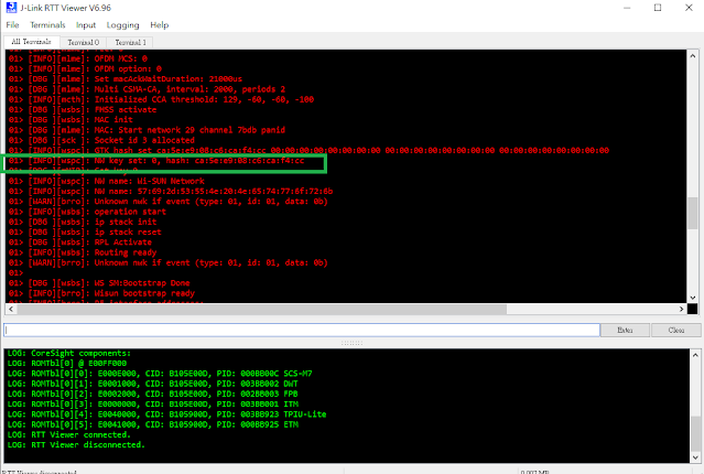
1.5 Check Start J-Link RTT Viewer output to get Wi-SUN network key, which we need to input this into Texas Instrument Wi-SUN device to join the same network.

2. Create and join Wi-SUN SoC Ping node into border router.

2.1 Create and build Wi-SUN SoC Ping example in Simplicity Studio v5.

2.2 Download Wi-SUN SoC Ping example firmware to second BRD4170A radio board and launch another console to connect to Wi-SUN network.

2.3 After joining success, you can ping border router from console with CLI command "wisun ping fd00:6172:6d00:0:92fd:9fff:fe6d:5e63".


3. Build and run Wi-SUN coap node on Texas Instrument CC1312R7 to join Silicon Labs border router.

3.1 Install Texas Instrument CCS10.4 and SimpleLink SDK simplelink_cc13x2_26x2_sdk_5_20_00_52 to import ns_coap_node example for CC1312R7 LaunchPad.

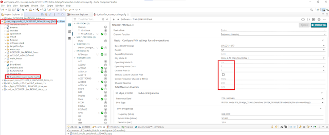
3.2 Setup Pre-Shared Network Key in sysconf with network key get in step 1.5

3.3 Since we use Wi-SUN 1b mode, the preamble should be 64 bits for Wi-SUN 1b mode. TI Wi-Sun Stack seems put this with incorrect preamble count. You should revise it to 8 bytes otherwise it cannot interoperate with Silicon Labs Wi-SUN Stack.

3.4 Copy the following certificates (can be copied from wisun_custom_certificates.h in Silicon Labs Wi-SUN SoC Ping example) and add related codes into application.c of Texas Instrument ns_coap_node example.

const uint8_t WISUN_ROOT_CERTIFICATE_SL[] = {
    "-----BEGIN CERTIFICATE-----\r\n"
    "-----Copy Wi-Sun Root Certificate from SL wisun_custom_certificates.h\r\n"
    "-----END CERTIFICATE-----"
};

const uint8_t WISUN_CLIENT_CERTIFICATE_SL[] = {
    "-----BEGIN CERTIFICATE-----\r\n"
    "-----Copy Wi-Sun Client Certificate from SL wisun_custom_certificates.h\r\n"
    "-----END CERTIFICATE-----"
};

const uint8_t WISUN_CLIENT_KEY_SL[] = {
    "-----BEGIN PRIVATE KEY-----\r\n"
    "-----Copy Wi-Sun Client Key from SL wisun_custom_certificates.h\r\n"
    "-----END PRIVATE KEY-----"
};
 

#define MBED_CONF_APP_OWN_CERTIFICATE                               WISUN_CLIENT_CERTIFICATE_SL
#define MBED_CONF_APP_OWN_CERTIFICATE_KEY                           WISUN_CLIENT_KEY_SL
#define MBED_CONF_APP_ROOT_CERTIFICATE                              WISUN_ROOT_CERTIFICATE_SL

wisun_tasklet_remove_trusted_certificates();
wisun_tasklet_set_trusted_certificate(MBED_CONF_APP_ROOT_CERTIFICATE,strlen((const char *) MBED_CONF_APP_ROOT_CERTIFICATE) + 1);
wisun_tasklet_remove_own_certificates();
wisun_tasklet_set_own_certificate(MBED_CONF_APP_OWN_CERTIFICATE, strlen((const char *) MBED_CONF_APP_OWN_CERTIFICATE) + 1,
                                      MBED_CONF_APP_OWN_CERTIFICATE_KEY, strlen((const char *) MBED_CONF_APP_OWN_CERTIFICATE_KEY) + 1);


3.5 Build and download ns_coap_node example into CC1312R7 LaunchPad. Start Application UART console of CC1312R7 to make sure it join Silicon Labs Wi-SUN border router network.

4. We can use CLI command "wisun ping fe80:0000:0000:0000:0212:4b00:14f7:d11a" from Silicon Labs Wi-SUN SoC Ping node console to ping Texas Instrument CC1312R coap nod to get response. They interoperate each other now.


Tuesday, August 25, 2020

Build OpenThread Sleepy End Device doorlock prototype to test with Rasperry Pi OpenThread Border Router

The following steps show how to build OpenThread Sleepy End Device doorlock prototype to test with Rasperry Pi OpenThread Border Router

1. Build OpenThread Sleepy End Device doorlock prototype for TI LAUNCHXL-CC26X2R1

1.1 Download/Install TI CCS 10.1 and SIMPLELINK-CC13X2-26X2-SDK v4.20.00.35.

1.2 Import thread door_lock example from C:\ti\simplelink_cc13x2_26x2_sdk_4_20_00_35\examples\rtos\CC26X2R1_LAUNCHXL\thread\door_lock

1.3 Set door_lock as Sleepy End Device from sysconfig.


1.4 Add the following codes in tiop_ui.c for providing API to output IPv6 address to UART console.

inline uint16_t Swap16(uint16_t v)
{
    return (((v & 0x00ffU) << 8) & 0xff00) | (((v & 0xff00U) >> 8) & 0x00ff);
}
 

inline uint16_t HostSwap16(uint16_t v)
{
    return Swap16(v);
}

void tiopCUIOutputIp6Address(otIp6Address aAddress)
{
    CUI_statusLinePrintf(
        clientHandle, nwkInfoLine1,
        "[" CUI_COLOR_GREEN "IPv6" CUI_COLOR_RESET "] %s - %x:%x:%x:%x:%x:%x:%x:%x",
        "Addr",
        HostSwap16(aAddress.mFields.m16[0]), HostSwap16(aAddress.mFields.m16[1]),
                HostSwap16(aAddress.mFields.m16[2]), HostSwap16(aAddress.mFields.m16[3]), HostSwap16(aAddress.mFields.m16[4]),
                HostSwap16(aAddress.mFields.m16[5]), HostSwap16(aAddress.mFields.m16[6]), HostSwap16(aAddress.mFields.m16[7]));
}

1.5 Add the following line to expose API tiopCUIOutputIp6Address in tiop_ui.h.

extern void tiopCUIOutputIp6Address(otIp6Address aAddress);

1.6 Add the following line in "case DoorLock_evtKeyRight:..." of processEvent (doorlock.c) to output IPv6 address when right button is pressed.

tiopCUIOutputIp6Address(*(otThreadGetRloc(OtInstance_get())));

1.7 Build and download sleepy door_lock firmware into LAUNCHXL-CC26X2R1.


2. Setup OpenThread Border Router and libcoap on Raspberry Pi.

2.1 Refer to this link to setup OpenThread Border Router on Raspberry Pi.

2.2 Run the following command in Raspberry Pi console to setup libcoap.

      sudo apt install autoconf automake libtool
      git clone --depth 1 --recursive -b dtls https://github.com/home-assistant/libcoap.git
      cd libcoap
      ./autogen.sh
      ./configure --disable-documentation --disable-shared --without-debug CFLAGS="-D COAP_DEBUG_FD=stderr"
      make
      sudo make install

3. Use the following commands on Raspberry Pi console and start sleepy door_lock to join thread network. Then, press right button on LAUNCHXL-CC26X2R1 to print IPv6 address of sleepy door_lock.

sudo ot-ctl commissioner start
sudo ot-ctl commissioner joiner add 00124b001ca16238 DRRLCK1

4. Use the following command to request lock state of sleepy door_lock from border router.

coap-client -m get coap://[fd11:1111:1122:0:0:ff:fe00:ec08]/doorlock/lockstate

5. Use the following command to change lock state of sleepy door_lock from border router.

coap-client -m post coap://[fd11:1111:1122:0:0:ff:fe00:ec08]/doorlock/lockstate -e unlock


Sunday, July 29, 2018

660 Zigbee devices in the same Zigbee network!


660 Zigbee devices in the same Zigbee network now!!! This time, we have total 660 Zigbee devices, including 130 ZRs (Smart Plugs) and 530 ZEDs (PIR motion sensors, Door Contact sensors, and Smoke Detectors), joined to a single Zigbee network. The solution is based on TI CC2530.


Wednesday, November 26, 2014

How to output PWM from CC2530/CC2541

Refer to CC253x/4x User's Guide. The following sample code can send PWM to P1_4.


  PERCFG &= (~(0x20)); // Select Timer 3 Alternative 1 location
  P2SEL |=0x20;
  P2DIR |= 0xC0;  // Give priority to Timer 1 channel2-3
  P1SEL |= BV(4);  // Set P1_4 to peripheral, Timer 1,channel 2
  P1DIR |= BV(4);

  T3CTL &= ~0x10;             // Stop timer 3 (if it was running)
  T3CTL |= 0x04;              // Clear timer 3
  T3CTL &= ~0x08;             // Disable Timer 3 overflow interrupts
  T3CTL |= 0x03;              // Timer 3 mode = 3 - Up/Down

  T3CCTL1 &= ~0x40;           // Disable channel 0 interrupts
  T3CCTL1 |= 0x04;            // Ch0 mode = compare
  T3CCTL1 |= 0x10;            // Ch0 output compare mode = toggle on compare

  T3CTL &= ~0xE0;   // Clear Prescaler divider value
  T3CTL |= 0xA0;    //Set Prescaler divider value = Tick frequency /32
  T3CC0 = 128;      //Set ticks = 128

  // Start timer
  T3CTL |= 0x10;

Then, the following example shows you how you output 6.5K PWM with 50% duty cycle to P1.1 with CC2530 Timer 1.

  PERCFG |= BV(6); // Select Timer 1 Alternative 2 location
  P2DIR = (P2DIR & ~0xC0) | 0x80; // Give priority to Timer 1
  P1SEL |= BV(1);  // Set P1_1 to peripheral

  T1CC0L = 0x3A;   // PWM signal period
  T1CC0H = 0x01;

  T1CC1L = 0x9D;  // PWM duty cycle
  T1CC1H = 0x00;

  T1CCTL1 = 0x1c;

  T1CTL |= (BV(2)|0x03); // divide with 128 and to do i up-down mode

Wednesday, December 4, 2013

CC2530/CC2541 ADC Howto in TI Z-Stack/BLE Stack

It is always a mystery to beginner to use ADC on CC2530/CC2541. Here, I post how to use TI Z-Stack/BLE Stack API to read ADC value on CC2530/CC2541. I hope this post can help anyone who struggles on CC2530/CC2541 ADC usage. In the followings, I show how to use P0_2 as ADC input, HAL_ADC_REF_125V as reference voltage, and HAL_ADC_RESOLUTION_10, HAL_ADC_RESOLUTION_12, HAL_ADC_RESOLUTION_14 as ADC resolution respectively.

1.  Read ADC value from P0_2 using HAL_ADC_REF_125V as reference voltage and HAL_ADC_RESOLUTION_10 as ADC resolution.

        uint16 adc_ain2=0;
        HalAdcSetReference(HAL_ADC_REF_125V);
        adc_ain2=HalAdcRead(HAL_ADC_CHN_AIN2,HAL_ADC_RESOLUTION_10);


The max measurable voltage of P0_2 is 1.15 because I am using HAL_ADC_REF_125V as reference voltage here. If the input voltage is larger than 1.15V, the ADC reading adc_ain2 will be always 511. If I connect P0_2 to 0.5V, I will have ADC reading adc_ain2=223. Then, we can convert the reading 223 to measured voltage using the following equation.
measured voltage = 1.15x223/511=0.501...

2. If I change  HAL_ADC_RESOLUTION_12 (the max reading is 2047) as ADC resolution and connect P0_2 to 0.5V, I will have ADC reading adc_ain2=886. Then, we can convert the reading 889 to measured voltage using the following equation.
measured voltage = 1.15x889/2047=0.499...


3. If I change  HAL_ADC_RESOLUTION_14 (the max reading is 8191) as ADC resolution and connect P0_2 to 0.5V, I will have ADC reading adc_ain2=3550. Then, we can convert the reading 3550 to measured voltage using the following equation.
measured voltage = 1.15x3550/8191=0.498...