Showing posts with label EFR32. Show all posts

Saturday, April 15, 2023

Amazon Sidewalk Test over BLE using Silcon Labs EFR32MG24 BRD4186C

Amazon Sidewalk is broadly announced in US market. It leverage exising Amazon devices such as Echo, Ring Alarm Panel, or DoorPhone. The following steps show you how to setup Silicon Labs EFR32MG24 radio board BRD4186C to test sending and receiving packets by Amazon Sidewalk. 

1. Setup my Amazon Echo 4th generation. Most important thing is that Amazon Sidewalk is only available in US region so your IP address needs to be in US region. If not, you have to setup VPN for this.

2. Connect BRD4186C to my desktop and start Simplicity Studio v5 to create "Amazon Sidewalk - SoC Bluetooth Hello Neighbor" project, which is available in Silicon Labs GSDK 4.2.2.

3. Add and revise the following code in on_sidewalk_msg_received to receive on/off command (1 as on and 0 as off) later from AWS IoT MQTT client to toggle LED0 on BRD4001A or BRD4002A mainboard.

#include <stdlib.h>
#include "sl_simple_led.h"

extern const sl_led_t sl_led_led0;

static void on_sidewalk_msg_received(const struct sid_msg_desc *msg_desc,
                                     const struct sid_msg *msg,
                                     void *context)
{
  char cmd;
  UNUSED(context);
  app_log_info("App - received message (type: %d, id: %u, size %u)", (int)msg_desc->type, msg_desc->id, msg->size);
  app_log_info("App - %s", (char *) msg->data);
  memcpy(&cmd, msg->data,1);
  if(cmd=='1'){
    sl_led_turn_on(&sl_led_led0);
    app_log_info("from YK App - on");
  }
  else if(cmd=='0'){
      sl_led_turn_off(&sl_led_led0);
      app_log_info("from YK App - off");
    }
}

4. Revise the following code in send_counter_update to send "YK Amazon Sidewalk test %d" when press button 1 on BRD4001A or BRD4002A mainboard.

char buffer[64];

static void send_counter_update(app_context_t *app_context)
{
  if (app_context->state == STATE_SIDEWALK_READY
      || app_context->state == STATE_SIDEWALK_SECURE_CONNECTION) {
    app_log_info("App - sending counter update: %d", app_context->counter);

    sprintf(buffer,"YK Amazon Sidewalk test %d\0", app_context->counter);
    struct sid_msg msg = {
      .data = (uint8_t *)buffer,//&app_context->counter,
      .size = strlen(buffer)//sizeof(uint8_t)
    };
    struct sid_msg_desc desc = {
      .type = SID_MSG_TYPE_NOTIFY,
      .link_type = SID_LINK_TYPE_ANY,
    };

    sid_error_t ret = sid_put_msg(app_context->sidewalk_handle, &msg, &desc);
    if (ret != SID_ERROR_NONE) {
      app_log_error("App - failed queueing data: %d", (int)ret);
    } else {
      app_log_info("App - queued data message id: %u", desc.id);
    }

    app_context->counter++;
  } else {
    app_log_error("App - sidewalk is not ready yet");
  }
}

5. Build and download "Amazon Sidewalk - SoC Bluetooth Hello Neighbor" firmware into BRD4186C. Also need to download bootloader into BRD4186C to make application work.

6. Login your Amazon "Identity and Access Management (IAM)" and go to "Security credentials" to create "access key ID" and "secret access key" for provision your Amazon Sidewalk device.

7. Refer to AWS Command Line Interface (CLI) to Install AWS CLI version 1.

8. Start a Dos console to run "aws configure" to input your "Security credentials" to create "access key ID" that are created in step 6.

9. Follow steps in Provision your Amazon Sidewalk Device.

10. Disconnect and reconnect USB cable from BRD4001A/BRD4002A to restart BRD4186C, and start RTT viewer. You should able to see your "Amazon Sidewalk - SoC Bluetooth Hello Neighbor" running on BRD4186C.

10. You can press button 0 on BRD4001A or BRD4002A mainboard to get connect and button 1 to send messages. You can refer to "Send Data"section in Interacting with the Cloud to use AWS MQTT client test to check message received.


11. For sending on/off message to control LED0 on BRD4001A or BRD4002A mainboard, you can refer to "Receive Data"section in Interacting with the Cloud to start a Dos console to use the following command to send on (or off) command.

aws iotwireless send-data-to-wireless-device --id=xxxx --transmit-mode 0 --payload-data="MQ==" --wireless-metadata "Sidewalk={Seq=1}"

If the device receives command from Amazon Sidewalk, it would pops the following message on RTT viewer and LED0 would be turned on (or off).

p.s. payload-data is Base64 encoded data. "MQ==" is equal to "1" which is used for on command in my code.

12. For power consumption, it's about 132uA when device is idle and about 810 uA when device is receiving message or sending message according to Energy Profiler. These power consumption numbers are quite satisfying for battery power device.


Thursday, April 13, 2023

How to add one extra endpoint for Matter/OpenThread Light.

The following steps show you how to add one extra endpoint for Matter/OpenThread Light with Silicon Labs EFR32MG24 BRD4187C radio board. 

1. Create MatterLightOverThread with Silicon Labs EFR32MG24 BRD4187C radio board first.

2. Start ZAP tool (Zigbee Cluster Configurator) and copy endpoint 1 to create endpoint 2.

3. Enable all required client->server commands for endpoint 2 of on/off and level cluster in ZAP tool.


4. Make a copy of LightingManager.h to LightingManager_ep2.h and LightingManager.cpp to LightingManager_ep2.cpp.

5. Add "#include "LightingManager_ep2.h"" and the following items for endpoint 2 in AppTask.h.

    static void ActionInitiated_ep2(LightingManager_ep2::Action_t aAction, int32_t aActor);
    static void ActionCompleted_ep2(LightingManager_ep2::Action_t aAction);
    static void UpdateClusterState_ep2(intptr_t context);

6. Add led2 for endpoint by clicking "Adding New Instances" in Simple LED SOFTWARE COMPONENTS and configure led2 to use PA05 which is pin 7 on EXP header of BRD4001A/BRD4002A mainboard.

7. Add "#define LIGHT_LED_EP2 &sl_led_led2" and "LEDWidget sLightLED_ep2;" for led light of endpoint 2 in AppTask.c.

8. Add implementation of ActionInitiated_ep2, ActionCompleted_ep2, and UpdateClusterState_ep2 in AppTask.c.

void AppTask::ActionInitiated_ep2(LightingManager_ep2::Action_t aAction, int32_t aActor)
{
    // Action initiated, update the light led
    bool lightOn = aAction == LightingManager_ep2::ON_ACTION;
    EFR32_LOG("Turning _ep2 light %s", (lightOn) ? "On" : "Off")

#ifdef ENABLE_WSTK_LEDS
    sLightLED_ep2.Set(lightOn);
#endif // ENABLE_WSTK_LEDS

#ifdef DISPLAY_ENABLED
    sAppTask.GetLCD().WriteDemoUI(lightOn);
#endif
#ifdef SL_CATALOG_SIMPLE_BUTTON_PRESENT
    if (aActor == AppEvent::kEventType_Button)
    {
        sAppTask.mSyncClusterToButtonAction = true;
    }
#endif
}

void AppTask::ActionCompleted_ep2(LightingManager_ep2::Action_t aAction)
{
    // action has been completed bon the light
    if (aAction == LightingManager_ep2::ON_ACTION)
    {
        EFR32_LOG("EP2 Light ON")
    }
    else if (aAction == LightingManager_ep2::OFF_ACTION)
    {
        EFR32_LOG("EP2 Light OFF")
    }
#ifdef SL_CATALOG_SIMPLE_BUTTON_PRESENT
    if (sAppTask.mSyncClusterToButtonAction)
    {
        chip::DeviceLayer::PlatformMgr().ScheduleWork(UpdateClusterState_ep2, reinterpret_cast<intptr_t>(nullptr));
        sAppTask.mSyncClusterToButtonAction = false;
    }
#endif
}

void AppTask::UpdateClusterState_ep2(intptr_t context)
{
    uint8_t newValue = LightMgr_ep2().IsLightOn();

    // write the new on/off value
    EmberAfStatus status = OnOffServer::Instance().setOnOffValue(2, newValue, false);

    if (status != EMBER_ZCL_STATUS_SUCCESS)
    {
        EFR32_LOG("ERR: updating ep2 on/off %x", status);
    }

9. Add kEventType_Light_ep2 enum behind kEventType_Light in AppEvent.h and use the following codes to replace original codes in LightActionEventHandler to support endpoint 2 light action.

    void AppTask::LightActionEventHandler(AppEvent * aEvent)
{
    bool initiated = false;
    LightingManager::Action_t action;
    LightingManager_ep2::Action_t action_ep2;
    int32_t actor;
    int32_t actor_ep2;
    CHIP_ERROR err = CHIP_NO_ERROR;

    if (aEvent->Type == AppEvent::kEventType_Light)
    {
        action = static_cast<LightingManager::Action_t>(aEvent->LightEvent.Action);
        actor  = aEvent->LightEvent.Actor;
    }
    else if (aEvent->Type == AppEvent::kEventType_Light_ep2)
      {
          action_ep2 = static_cast<LightingManager_ep2::Action_t>(aEvent->LightEvent.Action);
          actor_ep2  = aEvent->LightEvent.Actor;
      }
#ifdef SL_CATALOG_SIMPLE_BUTTON_PRESENT
    else if (aEvent->Type == AppEvent::kEventType_Button)
    {
        action = (LightMgr().IsLightOn()) ? LightingManager::OFF_ACTION : LightingManager::ON_ACTION;
        actor  = AppEvent::kEventType_Button;
    }
#endif
    else
    {
        err = APP_ERROR_UNHANDLED_EVENT;
    }

    if (err == CHIP_NO_ERROR)
    {
        if (aEvent->Type == AppEvent::kEventType_Light){
          initiated = LightMgr().InitiateAction(actor, action);

          if (!initiated)
          {
              EFR32_LOG("Action is already in progress or active.");
          }
        }
        else if (aEvent->Type == AppEvent::kEventType_Light_ep2)
        {
          initiated = LightMgr_ep2().InitiateAction(actor_ep2, action_ep2);

          if (!initiated)
          {
              EFR32_LOG("_ep2 Action is already in progress or active.");
          }
        }
    }
}

10. Add "#include "LightingManager_ep2.h"" ZclCallbacks.cpp and use the following codes in MatterPostAttributeChangeCallback function.

void MatterPostAttributeChangeCallback(const chip::app::ConcreteAttributePath & attributePath, uint8_t type, uint16_t size,
                                       uint8_t * value)
{
    ClusterId clusterId     = attributePath.mClusterId;
    AttributeId attributeId = attributePath.mAttributeId;
    EndpointId endpoint = attributePath.mEndpointId;
    ChipLogProgress(Zcl, "Cluster callback: " ChipLogFormatMEI, ChipLogValueMEI(clusterId));

    if (clusterId == OnOff::Id && attributeId == OnOff::Attributes::OnOff::Id)
    {
        //ChipLogProgress(Zcl, "<---YK---> MatterPostAttributeChangeCallback Endpoint %d on/off value=%d", endpoint, value);
        if(endpoint==1)
          LightMgr().InitiateAction(AppEvent::kEventType_Light, *value ? LightingManager::ON_ACTION : LightingManager::OFF_ACTION);
        else if(endpoint==2)
          LightMgr_ep2().InitiateAction(AppEvent::kEventType_Light_ep2, *value ? LightingManager_ep2::ON_ACTION : LightingManager_ep2::OFF_ACTION);
    }
    else if (clusterId == LevelControl::Id)
    {
        ChipLogProgress(Zcl, "Level Control attribute ID: " ChipLogFormatMEI " Type: %u Value: %u, length %u",
                        ChipLogValueMEI(attributeId), type, *value, size);

        // WIP Apply attribute change to Light
    }
    else if (clusterId == ColorControl::Id)
    {
        ChipLogProgress(Zcl, "Color Control attribute ID: " ChipLogFormatMEI " Type: %u Value: %u, length %u",
                        ChipLogValueMEI(attributeId), type, *value, size);

        // WIP Apply attribute change to Light
    }
    else if (clusterId == OnOffSwitchConfiguration::Id)
    {
        ChipLogProgress(Zcl, "OnOff Switch Configuration attribute ID: " ChipLogFormatMEI " Type: %u Value: %u, length %u",
                        ChipLogValueMEI(attributeId), type, *value, size);

        // WIP Apply attribute change to Light
    }
    else if (clusterId == Identify::Id)
    {
        ChipLogProgress(Zcl, "Identify attribute ID: " ChipLogFormatMEI " Type: %u Value: %u, length %u",
                        ChipLogValueMEI(attributeId), type, *value, size);
    }
}

11. Build and download MatterLightOverThread into BRD4187C

12. Join the MatterLightOverThread device into Matter/Thread network of Apple Home mini with Hoe App and you can see two endpoints in Home App to control them separately.


 p.s. for your references, on/off command received flow in Matter source code is like the followings:

InteractionModelEngine::OnMessageReceived
ProcessInvokeRequest
ProcessCommandDataIB
DispatchCommand
DispatchSingleClusterCommand
DispatchServerCommand
emberAfOnOffClusterOffCallback
OnOffServer::Instance().offCommand(commandPath);
OnOffServer::setOnOffValue
Attributes::OnOff::Set
emberAfWriteServerAttribute [#define emberAfWriteServerAttribute emberAfWriteAttribute (af.h)]
emberAfWriteAttribute
emAfWriteAttribute
MatterPostAttributeChangeCallback (ZclCallbacks.cpp)

Friday, December 23, 2022

Matter/OpenThread Border Router/Gateway Reality in the field by end of 2022

It's almost in the end of 2022 and Matter/OpenThread definitely would be noted as one of biggest event in IOT. The design philosophy of Matter is the convergence of IOT so end user won't have panic selecting and using IOT appliances on the markets. Until now, there are lots of company announcing Matter Border Router/Gateway support. I try to figure out or test the reality of such event and hope can help others further understanding this topic.

1. Apple: support Matter to its devices with iOS 16.1, iPadOS 16.1, macOS Ventura, watchOS 9.1, tvOS 16.1, and HomePod 16.1 software updates on Nov. 2022.I try to build Matter/OpenThread light-app, Thermostat, and light-switch-app applications on Silicon Labs EFR32 SoC and all of them work fluently. Incredible! Don't have Matter/Wifi device to test if it work but I would guess it works since Matter/OpenThread works in my tests.

2. Google: release firmware update including the original Google Home speaker, Google Home Mini, Nest Mini, Nest Audio, Nest Hub (1st and 2nd gen), Nest Hub Max, and the new Nest Wifi Pro to support Matter on Dec. 2022. I also use Matter/OpenThread light-app, Thermostat, and light-switch-app applications on Silicon Labs EFR32 SoC to test this. However, it always stops at the end of commissioning process and I believe this is bug and compatibility issue from Google. Since Matter/OpenThread devuce cannot work, I won't expect Matter/Wifi device would work but I welcome someone provides information to prove it works.

Add on Jan. 30th 2023, you can add Matter/OpenThread light-app to Goggle Nest Hub Max by using Android 13 camera to scan QR-code on device.

3. Amazon:  rolling out Matter/Wifi support for 17 Echo devices on Dec. 2022 too and an Android phone is required for Matter setup. Amazon also says that Matter/OpenThread and iOS support will arrive sometime in 2023. Since I don't have Matter/Wifi device, I cannot prove if it works. I also welcome someone provides information to prove it works.

4. Philips: announce they will release new firmware for Hue Bridge in the first quarter of 2023.

5. Samsung: rolling out an OTA update for SmartThings v2 and v3 hubs to add Matter compatibility (via Samsung). The v2 hub will let you control Matter-compatible smart home devices over Wi-Fi and Ethernet, with Thread border router support limited to the v3 hub and SmartThings dongle. I don't have SmartThings hubs to test this and I don't see anyone reports it works by surfing/Google on Internet. I also welcome someone provides information to prove it works.

6.Aqara: users will first gain access to Matter in December 2022 via the Aqara Hub M2 through an OTA (over-the-air) update, which will allow existing Aqara Zigbee devices to become compatible with Matter. I don't have Aqara Hub M2 to test this and also don't see anyone reports this works by surfing/Google on Internet. I also welcome someone provides information to prove it works.

It seems lots of company announcing Matter support but it not actually happens in the field. Maybe it's still too early to judge anything on Matter protocol now. If you are interested in Matter device, I would suggest you to watch and monitor it for now. I would guess 2023 Q2 might be a good timing to check the Matter reality again.

By the way, you won't see much news or press from Apple Matter support but actually they integrate HomeKit with Matter/Thread seamlessly. I would give them a thumb up for solid technology to support this. If you have money, go to buy Apple stock before you buy Apple products.

Friday, October 28, 2022

Build and run Matter and OpenThread lighting-app on EFR32MG24 to work with Apple HomePod Mini and iPhone Home App.

The following steps show you how to build and run Matter and OpenThread lighting-app on EFR32MG24 to work with Apple HomePod Mini and iPhone Home App.

1. Refer to steps 1 and 2 in How to setup and build Matter/CHIP EFR32 Lighting Example on Ubuntu 20.04 to setup Ubuntu 20.04 build environment and git master Matter source codes.

2. Switch to v1.0-branch and workable commit.

    cd connectedhomeip/
    git fetch origin
    git branch -a
    git checkout -b v1.0 remotes/origin/v1.0-branch
    git submodule update --init --recursive
    git checkout 561d23d0db215a99705ff0696e73853c8edf11b2
 

3. Build lighting-app for BRD4186C

    ./scripts/examples/gn_efr32_example.sh ./examples/lighting-app/efr32/ ./out/lighting-app BRD4186C

4. Download chip-efr32-lighting-example.hex (can be found under out/lighting-app/BRD4186C) in to BRD4186C+BRD4001A.

5. Make sure your Apple HomePod Mini and iPhone are update to OS 16.1.

6. Start Home App on your iPhone and scan the QR code on LCD of BRD4186C+BRD4001A. Following Home App wizard to complete settings.


7. You can have the Matter enable Light connecting with HomePod Mini and control it with iPhone Home App.

P.S. You can add the following code into AppTask::Init() in AppTask.c to print URL on RTT viewer output to generate QR code on browser.

PrintOnboardingCodes(chip::RendezvousInformationFlags(chip::RendezvousInformationFlag::kBLE));

P.S. You can use the following command to build lock-app SED for low power device test.

./scripts/examples/gn_efr32_example.sh ./examples/lock-app/efr32/ ./out/lock-app_SED BRD4186C --sed "chip_detail_logging=false chip_automation_logging=false chip_progress_logging=false is_debug=false show_qr_code=true chip_build_libshell=false disable_lcd=false enable_openthread_cli=false"

Friday, August 5, 2022

How to create periodic timer event and use iADC for EFR32 series 2 to do battery voltage monitor in GSDK 4.x and EmberZnet 7.x

How to create periodic timer event and use iADC for EFR32 series 2 to do battery voltage monitor in GSDK 4.x and EmberZnet 7.x

1. Add the following code in app.c

#define _IADC_

#ifdef _IADC_
#include "em_device.h"
#include "em_chip.h"
#include "em_cmu.h"
#include "em_iadc.h"
#include "em_gpio.h"
#endif //#ifdef _IADC_

#ifdef _IADC_
#define CLK_SRC_ADC_FREQ          20000000 // CLK_SRC_ADC
#define CLK_ADC_FREQ              10000000 // CLK_ADC - 10MHz max in normal mode
/*
 * Specify the IADC input using the IADC_PosInput_t typedef.  This
 * must be paired with a corresponding macro definition that allocates
 * the corresponding ABUS to the IADC.  These are...
 *
 * GPIO->ABUSALLOC |= GPIO_ABUSALLOC_AEVEN0_ADC0
 * GPIO->ABUSALLOC |= GPIO_ABUSALLOC_AODD0_ADC0
 * GPIO->BBUSALLOC |= GPIO_BBUSALLOC_BEVEN0_ADC0
 * GPIO->BBUSALLOC |= GPIO_BBUSALLOC_BODD0_ADC0
 * GPIO->CDBUSALLOC |= GPIO_CDBUSALLOC_CDEVEN0_ADC0
 * GPIO->CDBUSALLOC |= GPIO_CDBUSALLOC_CDODD0_ADC0
 *
 * ...for port A, port B, and port C/D pins, even and odd, respectively.
 */
#define IADC_INPUT_0_PORT_PIN     iadcPosInputAvdd;
#define IADC_INPUT_1_PORT_PIN     iadcNegInputGnd;

#define IADC_INPUT_0_BUS          BBUSALLOC
#define IADC_INPUT_0_BUSALLOC     GPIO_BBUSALLOC_BEVEN0_ADC0
#define IADC_INPUT_1_BUS          BBUSALLOC
#define IADC_INPUT_1_BUSALLOC     GPIO_BBUSALLOC_BODD0_ADC0

/*******************************************************************************
 ***************************   GLOBAL VARIABLES   *******************************
 ******************************************************************************/

static volatile int32_t sample;
static volatile double singleResult; // Volts

static sl_sleeptimer_timer_handle_t bat_volt_read_periodic_timer;
static void bat_volt_read_periodic_timer_callback(sl_sleeptimer_timer_handle_t *handle, void *data)
{
  (void)handle;
  (void)data;
  // Start IADC conversion
  IADC_command(IADC0, iadcCmdStartSingle);

  // Wait for conversion to be complete
  while((IADC0->STATUS & (_IADC_STATUS_CONVERTING_MASK
              | _IADC_STATUS_SINGLEFIFODV_MASK)) != IADC_STATUS_SINGLEFIFODV); //while combined status bits 8 & 6 don't equal 1 and 0 respectively

  // Get ADC result
  sample = IADC_pullSingleFifoResult(IADC0).data;

  // Calculate input voltage:
  // For differential inputs, the resultant range is from -Vref to +Vref, i.e.,
  // for Vref = VBGR = 2.42V, and with analog gain = 0.5, 12 bits represents
  // 4.84V full scale IADC range.
  singleResult = (sample * 4.84) / 0xFFF;

}
/**************************************************************************//**
 * @brief  Initialize IADC function
 *****************************************************************************/
void initIADC (void)
{
  // Declare init structs
  IADC_Init_t init = IADC_INIT_DEFAULT;
  IADC_AllConfigs_t initAllConfigs = IADC_ALLCONFIGS_DEFAULT;
  IADC_InitSingle_t initSingle = IADC_INITSINGLE_DEFAULT;
  IADC_SingleInput_t initSingleInput = IADC_SINGLEINPUT_DEFAULT;

  // Enable IADC0 and GPIO clock branches

  /* Note: For EFR32xG21 radio devices, library function calls to
   * CMU_ClockEnable() have no effect as oscillators are automatically turned
   * on/off based on demand from the peripherals; CMU_ClockEnable() is a dummy
   * function for EFR32xG21 for library consistency/compatibility.
   */
  CMU_ClockEnable(cmuClock_IADC0, true);
  CMU_ClockEnable(cmuClock_GPIO, true);

  // Reset IADC to reset configuration in case it has been modified by
  // other code
  IADC_reset(IADC0);

  // Select clock for IADC
  CMU_ClockSelectSet(cmuClock_IADCCLK, cmuSelect_FSRCO);  // FSRCO - 20MHz

  // Modify init structs and initialize
  init.warmup = iadcWarmupKeepWarm;

  // Set the HFSCLK prescale value here
  init.srcClkPrescale = IADC_calcSrcClkPrescale(IADC0, CLK_SRC_ADC_FREQ, 0);

  // Configuration 0 is used by both scan and single conversions by default
  // Use internal bandgap (supply voltage in mV) as reference
  initAllConfigs.configs[0].reference = iadcCfgReferenceInt1V2;
  initAllConfigs.configs[0].vRef = 1210;
  initAllConfigs.configs[0].analogGain = iadcCfgAnalogGain1x;

  // Divides CLK_SRC_ADC to set the CLK_ADC frequency
  initAllConfigs.configs[0].adcClkPrescale = IADC_calcAdcClkPrescale(IADC0,
                                             CLK_ADC_FREQ,
                                             0,
                                             iadcCfgModeNormal,
                                             init.srcClkPrescale);

  // Assign pins to positive and negative inputs in differential mode
  initSingleInput.posInput   = IADC_INPUT_0_PORT_PIN;
  initSingleInput.negInput   = IADC_INPUT_1_PORT_PIN;

  // Initialize the IADC
  IADC_init(IADC0, &init, &initAllConfigs);

  // Initialize the Single conversion inputs
  IADC_initSingle(IADC0, &initSingle, &initSingleInput);

  // Allocate the analog bus for ADC0 inputs
  GPIO->IADC_INPUT_0_BUS |= IADC_INPUT_0_BUSALLOC;
  GPIO->IADC_INPUT_1_BUS |= IADC_INPUT_1_BUSALLOC;
}
#endif//#ifdef _IADC_

2. Add the following codes in emberAfMainInitCallback

#ifdef _IADC_
  initIADC();
  sl_sleeptimer_start_periodic_timer(&bat_volt_read_periodic_timer, 1000, bat_volt_read_periodic_timer_callback, NULL, 0, 0);
#endif //#ifdef _IADC_

3. Battery voltage input to AVDD would be read to singleResult in bat_volt_read_periodic_timer_callback every second.

Thursday, August 4, 2022

How to setup and build Matter/CHIP EFR32 Lighting Example on Ubuntu 20.04.

The following steps show you how to setup and build Matter/CHIP EFR32 Lighting Example on Ubuntu 20.04.

1. Install necessary packages.

sudo apt-get install -y git gcc g++ pkg-config libssl-dev libdbus-1-dev libglib2.0-dev libavahi-client-dev ninja-build python3-venv python3-dev python3-pip unzip libgirepository1.0-dev libcairo2-dev libreadline-dev
 
2. Get Matter/CHIP source codes.

git clone --recurse-submodules https://github.com/project-chip/connectedhomeip
 

3. Enter Matter/CHIP source folder and build Matter/CHIP EFR32 Lighting Example


    3.1 run "cd connectedhomeip/"
 
    3.2 run "source scripts/activate.sh"
 
    3.3 run "./scripts/examples/gn_efr32_example.sh ./examples/lighting-app/efr32/ ./out/lighting-app BRD4161A"


4. Get chip-efr32-lighting-example.s37 under /connectedhomeip/out/lighting-app/BRD4161A to program it via Simplicity Flash Programmer or Commander.


5. You can see QR code on BRD4001A LCD and execute CLI command on serial console.

Friday, June 17, 2022

How to intercept ZDO leave request in EmberZnet.

The following steps show you how to intercept ZDO leave request in EmberZnet.

1. Enable Packet Handoff plugin.

2. Use emberAfIncomingPacketFilterCallback in project callbacks.

3. Add the following code to intercept ZDO leave request.

uint8_t* cmd;
EmberPacketAction emberAfIncomingPacketFilterCallback(EmberZigbeePacketType packetType, uint8_t* packetData, uint8_t* size_p, void* data)
{
  if(packetType == EMBER_ZIGBEE_PACKET_TYPE_ZDO){

      emberAfZdoPrintln("Receive EMBER_ZIGBEE_PACKET_TYPE_ZDO");
      emberAfZdoPrintBuffer(data,sizeof(data), true);
      cmd=(uint8_t*)data;
      if((cmd[2])==0x34 && (cmd[3])==0x00)
        emberAfZdoPrintln("-----------Receive ZDO Leave Request------------------------");
   }
  return EMBER_ACCEPT_PACKET;
}

Tuesday, May 31, 2022

How to use custom and increment token in Silicon Labs GSDK 4.x and EmberZnet 7.x

The following steps 2-4 show you how to use custom basic token and steps 5-7 show you how to use custom increment token in Silicon Labs GSDK 4.x and EmberZnet 7.x.

1. Turn on "Enable Custom Tokens" in Token Manager.


2.Add the following codes to sl_custom_token_header.h.

        #define NVM3KEY_BASICTOKEN1 (NVM3KEY_DOMAIN_USER | 0x4100)
        #define BASICTOKEN1_DEFAULT  0
        #ifdef DEFINETYPES
        typedef uint16_t tokTypeBasicToken1;
        #endif
        #ifdef DEFINETOKENS
        DEFINE_BASIC_TOKEN(BASICTOKEN1,
                                                  tokTypeBasicToken1,
                                                  BASICTOKEN1_DEFAULT)
        #endif

3. Implement counter incrementing and store to custom token TOKEN_BASICTOKEN1 when button is pressed in app.c. Add related code in sl_button_on_change.

void sl_button_on_change(const sl_button_t *handle)
{
  uint16_t cnt;
  if (sl_button_get_state(handle) == SL_SIMPLE_BUTTON_RELEASED) {
      sl_token_get_data(NVM3KEY_BASICTOKEN1, 0x7f, &cnt, sizeof(cnt));
      cnt++;
      sl_token_set_data(NVM3KEY_BASICTOKEN1, 0x7f, &cnt, sizeof(cnt));
  }
}

4. Build and download application into EFR32 to test counter read and set with increment in custom token.
 

5. Add the following codes to sl_custom_token_header.h.         

    #define NVM3KEY_COUNTERTOKEN1 (NVM3KEY_DOMAIN_USER | 0x4104)
    #define COUNTERTOKEN1_DEFAULT 0
    #ifdef DEFINETYPES
        typedef uint32_t tokTypeCounterToken1;
    #endif
    #ifdef DEFINETOKENS
        DEFINE_COUNTER_TOKEN(COUNTERTOKEN1,
                                                         tokTypeCounterToken1,
                                                         COUNTERTOKEN1_DEFAULT)
    #endif

6. Implement counter incrementing using increment token by adding related code in sl_button_on_change.

    void sl_button_on_change(const sl_button_t *handle)    
    {
      uint32_t buf;
      if (sl_button_get_state(handle) == SL_SIMPLE_BUTTON_RELEASED) {
          sl_token_get_data(NVM3KEY_COUNTERTOKEN1, 0x7f, &buf, sizeof(buf));
          sl_token_increment_counter(NVM3KEY_COUNTERTOKEN1);
          sl_token_get_data(NVM3KEY_COUNTERTOKEN1, 0x7f, &buf, sizeof(buf));
      }
    }
 7. Build and download application into EFR32 to test increment counter token when button is pressed

Friday, February 11, 2022

Build and run OpenThread Border Router for NXP i.MX6ULL with Silicon Labs EFR32 as RCP

This tutorial shows you how to build and run OpenThread Border Router for NXP i.MX6ULL with Silicon Labs EFR32 as RCP.

1. Setup build environment and build OpenThread Border Router for NXP i.MX6ULL EVK.

 sudo apt-get install -y gcc make perl curl nodejs npm
  • 1.3 Setup Yocto build environment.
mkdir ~/bin
curl http://commondatastorage.googleapis.com/git-repo-downloads/repo > ~/bin/repo
chmod a+x ~/bin/repo
export PATH=${PATH}:~/bin

sudo update-ca-certificates
mkdir yocto-otbr
cd yocto-otbr
git config --global user.email "youremail@email.com"
git config --global user.name "yourname"
repo init -u https://source.codeaurora.org/external/imx/imx-manifest -b imx-linux-hardknott -m imx-5.10.35-2.0.0.xml
repo sync
  • 1.4 Integrate the meta-matter recipe into the Yocto code base
cd yocto-otbr/sources
git clone https://github.com/NXPmicro/meta-matter.git
  • 1.5 Install necessary package to build the Yocto Project.
sudo apt-get install -y gawk wget git-core diffstat unzip texinfo gcc-multilib build-essential chrpath socat cpio python3 python3-pip python3-pexpect xz-utils debianutils iputils-ping python3-git python3-jinja2 libegl1-mesa libsdl1.2-dev pylint3 xterm
  • 1.6 Download 0001-Add-TUN-device-support-for-arm.patch into yocto-otbr/sources/meta-imx folder and run the following git command to patch it (This will build /dev/net/tun on i.MX6ULL system for otbr-agent).
git am -3 0001-Add-TUN-device-support-for-arm.patch
  • 1.7 Generate the Yocto image with OpenThread Border Router support.
MACHINE=imx6ullevk DISTRO=fsl-imx-xwayland source sources/meta-matter/tools/imx-iot-setup.sh bld-xwayland
bitbake imx-image-multimedia
  • 1.8 After previous two commands are excuted successfully, the Yocto image imx-image-multimedia-imx6ullevk.wic.bz2 will be generated under yocto-otbr/bld-xwayland/tmp/deploy/images/imx6ullevk/. imx-image-multimedia-imx6ullevk.wic.bz2 should be unzip to imx-image-multimedia-imx6ullevk.wic.
 
  • 1.9 Use "ls /dev/sd*" to check the sd card name. In my , it's "sdb" Use dd command to program imx-image-multimedia-imx6ullevk.wic.bz2 to a microSD.
 sudo dd if=imx-image-multimedia-imx6ullevk.wic of=/dev/sdb bs=4096 conv=fsync status=progress
  •  1.10 After previous step is done, the microSD card can be used to boot i.MX6ULL EVK with OpenThread Border Router capability.
 

2. Download OT-RCP into Silicon Labs BRD4161A (EFR32 radio board) using Simplicity Studio v5.

  • 2.1 Instead of building OT-RCP for Silicon Labs BRD4161A by myself, I install Simplicity Studio v5 and Gecko SDK Suite v3.2.3 with OpenThread 1.2.3.0


  • 2.2 Download prebuilt OT-RCP into Silicon Labs BRD4161A directly.


3. Connect NXP i.MX6ULL EVK with Silicon Labs EFR32 as RCP to test OpenThread Border Router.

  • 3.1 Connect Silicon Labs BRD4161A+BRD4001A to i.MX6ULL EVK with USB cable and put the the microSD (built in step 1) to power on i.MX6ULL EVK.
 

  • 3.2 Use root to login i.MX6ULL EVK debug console and run the following command to start otbr-agent
 otbr-agent -I wpan0 -B eth0 spinel+hdlc+uart:///dev/ttyACM0 &
 
P.S.Since we use Silicon Labs BRD4161A+BRD4001A, it should emulate ttyACM0 after connecting to i.MX6ULL EVK with USB cable. If you use othe OT-RCP hardware, you might need to check physical device name that is emulated by your hardware.
  • 3.3 Run ot-ctl, which is a command line utility provided with OTBR. It is used to communicate with the Thread PAN interface (default is wpan0) that otbr-agent is bound to in the RCP design, to start test everything.
 P.S. If you see "connection session failed: No such file or directory" problem when running ot-ctl, you can use "cat /var/log/syslog" to check what's wrong with otbr-agent.
 

  • 3.4 You can refer to step 5, 6, and 7 in this post to test OTBR and an OT-CLI-FTD node.


P.S. Thanks Elven Wang @NXP and Jonathan Hui @Google for their great help to make all of these work together. The followings are reference links of previous works that help me lots.

https://github.com/openthread/ot-br-posix/issues/1200#

https://github.com/NXPmicro/meta-matter

Wednesday, January 5, 2022

CLI command in EmberZnet to send IAS WD start warning command

 Using the following CLI command in EmberZnet to send IAS WD start warning command

//IAS WD Cluster: 0x0502
//ZCL header 01(Frame Control Byte) 0A (Transcation Seq no.) 00 (Command ID - Start Warning)
//ZCL Payload 10(0001(4 bits): Burglar mode 00(2 bits): Strobe/No 00(2 bits): Siren Level/low) FF00(Warning duration) 10(Strobe duty cycle) 00(Strobe level/low)
// Refer to section 8.4.2.3 in ZCL specification for details.

raw 0x502 {010A0010FF001000}

//0xB19D is short address of WD device and both 1 are source and destination endpoint.
send 0xB19D 1 1

Tuesday, December 7, 2021

Prototype OpenThread/HomeKit SwitchBot using Silicon Labs EFR32

Apple releases HomePod Mini to support Thread protocol. The following steps show you how easily to prototype an OpenThread/HomeKit SwitchBot using Silicon Labs EFR32:

1. Connect SLWSTK6000B to USB port of Desktop to start Simplicity Studio V5 and create "HomeKit Lightbulb DMP" in Launcher Tab


2. Configure "HomeKit Lightbulb DMP" as Sleepy MTD for power saving.

2.1 Revise FTD to MTD


2.2 Set "Enable reception when sleeping" to Disable in "UARTDRV Core"


2.3 Revise the following configurations in app.h.

#define kAccessorySleepInterval ((HAPTime) 5*HAPSecond)

#define kThreadDeviceType (kHAPPlatformThreadDeviceCapabilities_MTD)

2.4 Revise the following configurations in App_Base.h.

#define THREAD_CHILD_TIMEOUT_IN_SECONDS 9


3. Add the following codes in app.c

#include "em_device.h"
#include "em_cmu.h"
#include "em_emu.h"
#include "em_chip.h"
#include "em_gpio.h"
#include "em_timer.h"
//#include "bsp.h"

// Note: change this to set the desired output frequency in Hz
#define PWM_FREQ 50

// Note: change this to set the desired duty cycle (used to update CCVB value)
static volatile int dutyCyclePercent = 10;

// stores 1 msTicks from the SysTick timer
volatile uint32_t msTicks;

/**************************************************************************//**
 * @brief
 *    Interrupt handler for TIMER0 that changes the duty cycle
 *
 * @note
 *    This handler doesn't actually dynamically change the duty cycle. Instead,
 *    it acts as a template for doing so. Simply change the dutyCyclePercent
 *    global variable here to dynamically change the duty cycle.
 *****************************************************************************/
void TIMER0_IRQHandler(void)
{
  // Acknowledge the interrupt
  uint32_t flags = TIMER_IntGet(TIMER0);
  TIMER_IntClear(TIMER0, flags);

  // Update CCVB to alter duty cycle starting next period
  TIMER_CompareBufSet(TIMER0, 0, (TIMER_TopGet(TIMER0) * dutyCyclePercent) / 100);
}

/**************************************************************************//**
 * @brief GPIO initialization
 *****************************************************************************/
void initGpio(void)
{
  // Enable GPIO and clock
  CMU_ClockEnable(cmuClock_GPIO, true);

  // Configure PC10 (Expansion Header Pin 16) as output
  GPIO_PinModeSet(gpioPortC, 10, gpioModePushPull, 0);
}

/**************************************************************************//**
 * @brief
 *    TIMER initialization
 *****************************************************************************/
void initTimer(void)
{
  // Enable clock for TIMER0 module
  CMU_ClockEnable(cmuClock_TIMER0, true);

  // Configure TIMER0 Compare/Capture for output compare
  // Use PWM mode, which sets output on overflow and clears on compare events
  TIMER_InitCC_TypeDef timerCCInit = TIMER_INITCC_DEFAULT;
  timerCCInit.mode = timerCCModePWM;
  TIMER_InitCC(TIMER0, 0, &timerCCInit);

  // Route TIMER0 CC0 to location 15 and enable CC0 route pin
  // TIM0_CC0 #15 is GPIO Pin PC10
  TIMER0->ROUTELOC0 |=  TIMER_ROUTELOC0_CC0LOC_LOC15;
  TIMER0->ROUTEPEN |= TIMER_ROUTEPEN_CC0PEN;

  // Set top value to overflow at the desired PWM_FREQ frequency
  TIMER_TopSet(TIMER0, CMU_ClockFreqGet(cmuClock_TIMER0) / (8 * PWM_FREQ));

  // Set compare value for initial duty cycle
  TIMER_CompareSet(TIMER0, 0, (TIMER_TopGet(TIMER0) * dutyCyclePercent) / 100);

  // Initialize the timer
  TIMER_Init_TypeDef timerInit = TIMER_INIT_DEFAULT;
  timerInit.prescale = timerPrescale8;
  TIMER_Init(TIMER0, &timerInit);

  // Enable TIMER0 compare event interrupts to update the duty cycle
  TIMER_IntEnable(TIMER0, TIMER_IEN_CC0);
  NVIC_EnableIRQ(TIMER0_IRQn);
}

void sg90_on(void){
  dutyCyclePercent=25;
  initTimer();
  sl_udelay_wait(110000);
  dutyCyclePercent=10;
  initTimer();
  sl_udelay_wait(110000);
  dutyCyclePercent=25;
  initTimer();
  sl_udelay_wait(110000);
  CMU_ClockEnable(cmuClock_TIMER0, false);
  GPIO_PinModeSet(gpioPortC, 10, gpioModePushPull, 0);
}
void sg90_off(void){
  dutyCyclePercent=25;
  initTimer();
  sl_udelay_wait(130000);
  dutyCyclePercent=45;
  initTimer();
  sl_udelay_wait(130000);
  dutyCyclePercent=25;
  initTimer();
  sl_udelay_wait(130000);
  CMU_ClockEnable(cmuClock_TIMER0, false);
  GPIO_PinModeSet(gpioPortC, 10, gpioModePushPull, 0);
}

4. Add the following code to AppInitialize(), TurnOnLightBulb(), and TurnOffLightBulb() in app.c

4.1 Add initGpio() in AppInitialize().

4.2 Add sg90_on() in  TurnOnLightBulb().

4.3 Add sg90_off() in  TurnOffLightBulb().

5. Rename HomeKit device name to "OT HomeKit SwitchBot" in HomeKit Configurator


6. Connect SG90 servo motor to EXP Header (pin15-PC10) of SLWSTK6000B and build/download application into SLWSTK6000.


7. You need to have a HomePod mini, which supports OpenThread, and provision "OT HomeKit SwitchBot" with iPhone Home App.


8. Test it with Siri to trigger "OT HomeKit SwitchBot" to turn off/on my office light, which you can refer to the following video.


9. In Energy Profiler, you can see low average power consumption on "OT HomeKit SwitchBot" which is configured as Sleepy MTD and perfectly suitable for battery power.


Friday, October 15, 2021

How to use EmberZnet Cli command to send IAS WD command.

The following steps show you how to EmberZnet Cli command to send IAS WD command. 

1. Use any EFR32 to run SoC coordinator such as Z3Light example.

2. Use Cli "raw 0x502 {01000010000F0000}" to compose IAS WD command with raw data.

    Detail format of raw data in { } can be found in 2.4.1 General ZCL Frame Format of ZCL specification.

    01: Frame Control Field which can find details in section 2.4.1.1 of ZCL specification. 01 means "Command is specific or local to a cluster"

    00: Transaction sequence number

    00: Command identifier. Since we use "Command is specific or local to a cluster" in Frame Control Field. This command identifier should be matched to different cluster. In this case, it's IAS WD cluster (0x0502) Start warning (0x00) command which can be found in section 8.4.2.2 Commands Received of ZCL specification.

    10000F0000: Command Payload which is detailed in section 8.4.2.2.1.1 Payload Format of ZCL specification. 10 is Warning mode(Burglar)+Strobe(No)+Siren level(Low Level Sound). 000F is Warning Duration. 0000 is Strobe Duty Cycle and Strobe level.

3. Use Cli "send 0xD265 1 1" to send command to destination node with short address 0xD265 and endpoint 1.

4. You can verified the command is sent successfully on sniffer.


Tuesday, August 10, 2021

Interoperability test between Silicon Labs and Texas Instrument Wi-SUN Stack

Interoperability is most import in standard protocol implementation and deployment. In this test, I use two Silicon Labs EFR32 BRD4170A radio boards, one acts as Wi-SUN border router and another acts as ping node, and yet anther Texas Instrument CC1312R7 LaunchPad to act as Wi-SUN coap node to join. The following steps show you details interoperability test between Silicon Labs and Texas Instrument Wi-SUN Stack.

1. Setup Wi-SUN SoC Border Router on BRD4170A radio board.

1.1 Start Silicon Labs Simplicity Studio v5 and Install Wi-SUN Stack version 1.1.0.0


1.2 Download Wi-SUN SoC Border Router (running 1b mode) into one of BRD4170A radio board to act as border router.


1.3 Start J-Link RTT Viewer to get output log of  Wi-SUN SoC Border Router.


 1.4 Launch console of BRD4170A in Simplicity Studio v5 and use CLI command "start wisun" to start Wi-SUN network.

 
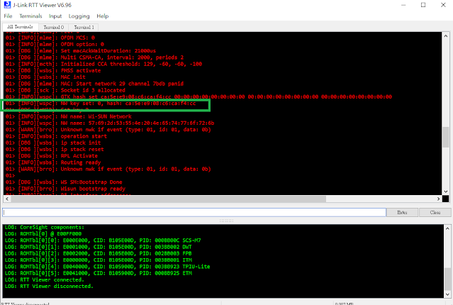
1.5 Check Start J-Link RTT Viewer output to get Wi-SUN network key, which we need to input this into Texas Instrument Wi-SUN device to join the same network.

2. Create and join Wi-SUN SoC Ping node into border router.

2.1 Create and build Wi-SUN SoC Ping example in Simplicity Studio v5.

2.2 Download Wi-SUN SoC Ping example firmware to second BRD4170A radio board and launch another console to connect to Wi-SUN network.

2.3 After joining success, you can ping border router from console with CLI command "wisun ping fd00:6172:6d00:0:92fd:9fff:fe6d:5e63".


3. Build and run Wi-SUN coap node on Texas Instrument CC1312R7 to join Silicon Labs border router.

3.1 Install Texas Instrument CCS10.4 and SimpleLink SDK simplelink_cc13x2_26x2_sdk_5_20_00_52 to import ns_coap_node example for CC1312R7 LaunchPad.

3.2 Setup Pre-Shared Network Key in sysconf with network key get in step 1.5

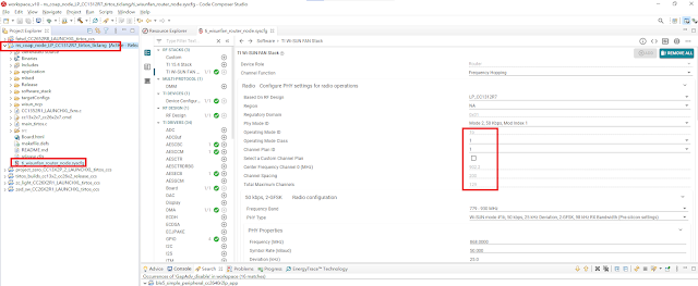
3.3 Since we use Wi-SUN 1b mode, the preamble should be 64 bits for Wi-SUN 1b mode. TI Wi-Sun Stack seems put this with incorrect preamble count. You should revise it to 8 bytes otherwise it cannot interoperate with Silicon Labs Wi-SUN Stack.

3.4 Copy the following certificates (can be copied from wisun_custom_certificates.h in Silicon Labs Wi-SUN SoC Ping example) and add related codes into application.c of Texas Instrument ns_coap_node example.

const uint8_t WISUN_ROOT_CERTIFICATE_SL[] = {
    "-----BEGIN CERTIFICATE-----\r\n"
    "-----Copy Wi-Sun Root Certificate from SL wisun_custom_certificates.h\r\n"
    "-----END CERTIFICATE-----"
};

const uint8_t WISUN_CLIENT_CERTIFICATE_SL[] = {
    "-----BEGIN CERTIFICATE-----\r\n"
    "-----Copy Wi-Sun Client Certificate from SL wisun_custom_certificates.h\r\n"
    "-----END CERTIFICATE-----"
};

const uint8_t WISUN_CLIENT_KEY_SL[] = {
    "-----BEGIN PRIVATE KEY-----\r\n"
    "-----Copy Wi-Sun Client Key from SL wisun_custom_certificates.h\r\n"
    "-----END PRIVATE KEY-----"
};
 

#define MBED_CONF_APP_OWN_CERTIFICATE                               WISUN_CLIENT_CERTIFICATE_SL
#define MBED_CONF_APP_OWN_CERTIFICATE_KEY                           WISUN_CLIENT_KEY_SL
#define MBED_CONF_APP_ROOT_CERTIFICATE                              WISUN_ROOT_CERTIFICATE_SL

wisun_tasklet_remove_trusted_certificates();
wisun_tasklet_set_trusted_certificate(MBED_CONF_APP_ROOT_CERTIFICATE,strlen((const char *) MBED_CONF_APP_ROOT_CERTIFICATE) + 1);
wisun_tasklet_remove_own_certificates();
wisun_tasklet_set_own_certificate(MBED_CONF_APP_OWN_CERTIFICATE, strlen((const char *) MBED_CONF_APP_OWN_CERTIFICATE) + 1,
                                      MBED_CONF_APP_OWN_CERTIFICATE_KEY, strlen((const char *) MBED_CONF_APP_OWN_CERTIFICATE_KEY) + 1);


3.5 Build and download ns_coap_node example into CC1312R7 LaunchPad. Start Application UART console of CC1312R7 to make sure it join Silicon Labs Wi-SUN border router network.

4. We can use CLI command "wisun ping fe80:0000:0000:0000:0212:4b00:14f7:d11a" from Silicon Labs Wi-SUN SoC Ping node console to ping Texas Instrument CC1312R coap nod to get response. They interoperate each other now.