Showing posts with label Simplicity Studio. Show all posts

Monday, April 29, 2024

Create and build Z-Wave - NCP Serial API Controller firmware for Z-Wave 800 ZGM230SA SoC

The following steps show you how to create and build Z-Wave - NCP Serial API Controller firmware for Z-Wave 800 ZGM230SA SoC.

Before you do anything, please make sure the secure firmware on your ZGM230SA is update to latest one. When I write this article, I use GSDK 4.4.1/Z-Wave SDK 7.20.2 and the latest secure firmware version for ZGM230SA is 2.2.4 for your reference.


To have Z-Wave - NCP Serial API Controller firmware working, you need to create and build Bootloader - NCP UART XMODEM first.The follow steps show you the details to create and build it.

1. Start Simplicity Studio v5 and go to Launcher perspective with your custom ZGM230SA borad connected or selecting ZGM230SAin "My Products" perspective. Create Bootloader - NCP UART XMODEM project as the following screenshot.

2. Go to "Bootloader UART Driver" and "GPIO activation" software component to configure UART TX/RX and SL_BTL_BUTTON pins according to your ZGM230SA custom board schematics.


3. Build and download Bootloader - NCP UART XMODEM firmware to your ZGM230SA custom board.

Then, you can create and build Z-Wave - NCP Serial API Controller firmware for your custom ZGM230SA board using the following steps:

1. Create Z-Wave - NCP Serial API Controller project as the following screenshot.

2. Go to "SerialAPI AppsHw" software component to configure UART TX/RX pins according to your ZGM230SA custom board schematics.

3. Build and download Z-Wave - NCP Serial API Controller firmware to your ZGM230SA custom board.

 After download both "Bootloader - NCP UART XMODEM" and "Z-Wave - NCP Serial API Controller firmware" firmware to your ZGM230S custom board, you can connect it with serial-to-USB convertor to your desktop and run Z-Wave PC controller to test it.

Thursday, September 7, 2023

Adding reporting period configuration in configuration command class to Z-Wave Multilevel sensor example running on BRD2603A/ZGM230S

The following steps and codes show you how to add a reporting period configuration with configuration command class to allow changing auto report period in Z-Wave Multilevel sensor example running on BRD2603A/ZGM230S

1. Create zwave_soc_multilevel_sensor in Simplicity Studio v5 with GSDK4.3.1/Z-Wave SDK 7.20.1.0.

2. Add 3rd parameter to "configurations:" section in MultilevelSensor.cc_config and SSv5 would rebuilt parameters in parameter_pool inside cc_configuration_config.c accordingly

    - name: "auto report period"
      number: 3
      file_id: 2
      info: "sensor auto reporting period"
      size: CC_CONFIG_PARAMETER_SIZE_32_BIT
      format: CC_CONFIG_PARAMETER_FORMAT_SIGNED_INTEGER
      min_value: 1
      max_value: 3600
      default_value: 1800
      altering_capabilities: 0
      read_only: 0
      advanced: 0

3. In CC_MultilevelSensor_Support.c, revise the following codes:

#define DEBUGPRINT
#include "DebugPrint.h"
#include "CC_Configuration.h"

SSwTimer cc_multilevel_sensor_autoreport_timer;
uint32_t autoreport_time = 30;

static void cc_multilevel_sensor_init(void)
{
  cc_multilevel_sensor_config_register_instances();
  cc_multilevel_sensor_init_all_sensor();
  ZAF_nvm_read(2, &autoreport_time, 4);
  DPRINTF("configuration_pool_init[2].parameters->attributes.default_value %d\r\n", (int)autoreport_time );

  AppTimerDeepSleepPersistentRegister(&cc_multilevel_sensor_autoreport_timer, false, cc_multilevel_sensor_autoreport_callback);
  AppTimerDeepSleepPersistentStart(&cc_multilevel_sensor_autoreport_timer, autoreport_time*1000);
}

static void cc_multilevel_sensor_autoreport_callback(SSwTimer *pTimer)
{
  UNUSED(pTimer);
  cc_multilevel_sensor_send_sensor_data();
  AppTimerDeepSleepPersistentStart(&cc_multilevel_sensor_autoreport_timer, autoreport_time*1000);
}

4. In CC_Configuration.c, add the following red lines into cc_configuration_set.

#include "SwTimer.h"
extern SSwTimer cc_multilevel_sensor_autoreport_timer;
extern uint32_t autoreport_time;
static cc_config_configuration_set_return_value
cc_configuration_set(uint16_t parameter_number,  cc_config_parameter_value_t* new_value, cc_config_parameter_size_t size)
{
  cc_config_configuration_set_return_value return_value = CC_CONFIG_RETURN_CODE_OK;
  bool io_transaction_result = false;
  bool is_value_in_range = false;
  bool has_to_break = false;
  cc_config_parameter_buffer_t parameter_buffer;

  if (parameter_number==3){
    autoreport_time = new_value->as_uint32;
    ZAF_nvm_write(2, &autoreport_time, 4);
    DPRINTF("cc_configuration_set para no. %d size %d: autoreport_time %d seconds\r\n", (int)parameter_number, (int)size, (int)autoreport_time );
    AppTimerDeepSleepPersistentStart(&cc_multilevel_sensor_autoreport_timer);
    AppTimerDeepSleepPersistentStart(&cc_multilevel_sensor_autoreport_timer, autoreport_time*1000);
  }

    for(uint16_t parameter_ix = 0 ; parameter_ix < configuration_pool->numberOfParameters ; parameter_ix++)
    {
...

}

5. Build and run firmware on BRD2603A to join zwave_soc_multilevel_sensor into PC controller. You can use CONFIGURATION_SET to change auto report period with parameter 3.


Saturday, April 15, 2023

Amazon Sidewalk Test over BLE using Silcon Labs EFR32MG24 BRD4186C

Amazon Sidewalk is broadly announced in US market. It leverage exising Amazon devices such as Echo, Ring Alarm Panel, or DoorPhone. The following steps show you how to setup Silicon Labs EFR32MG24 radio board BRD4186C to test sending and receiving packets by Amazon Sidewalk. 

1. Setup my Amazon Echo 4th generation. Most important thing is that Amazon Sidewalk is only available in US region so your IP address needs to be in US region. If not, you have to setup VPN for this.

2. Connect BRD4186C to my desktop and start Simplicity Studio v5 to create "Amazon Sidewalk - SoC Bluetooth Hello Neighbor" project, which is available in Silicon Labs GSDK 4.2.2.

3. Add and revise the following code in on_sidewalk_msg_received to receive on/off command (1 as on and 0 as off) later from AWS IoT MQTT client to toggle LED0 on BRD4001A or BRD4002A mainboard.

#include <stdlib.h>
#include "sl_simple_led.h"

extern const sl_led_t sl_led_led0;

static void on_sidewalk_msg_received(const struct sid_msg_desc *msg_desc,
                                     const struct sid_msg *msg,
                                     void *context)
{
  char cmd;
  UNUSED(context);
  app_log_info("App - received message (type: %d, id: %u, size %u)", (int)msg_desc->type, msg_desc->id, msg->size);
  app_log_info("App - %s", (char *) msg->data);
  memcpy(&cmd, msg->data,1);
  if(cmd=='1'){
    sl_led_turn_on(&sl_led_led0);
    app_log_info("from YK App - on");
  }
  else if(cmd=='0'){
      sl_led_turn_off(&sl_led_led0);
      app_log_info("from YK App - off");
    }
}

4. Revise the following code in send_counter_update to send "YK Amazon Sidewalk test %d" when press button 1 on BRD4001A or BRD4002A mainboard.

char buffer[64];

static void send_counter_update(app_context_t *app_context)
{
  if (app_context->state == STATE_SIDEWALK_READY
      || app_context->state == STATE_SIDEWALK_SECURE_CONNECTION) {
    app_log_info("App - sending counter update: %d", app_context->counter);

    sprintf(buffer,"YK Amazon Sidewalk test %d\0", app_context->counter);
    struct sid_msg msg = {
      .data = (uint8_t *)buffer,//&app_context->counter,
      .size = strlen(buffer)//sizeof(uint8_t)
    };
    struct sid_msg_desc desc = {
      .type = SID_MSG_TYPE_NOTIFY,
      .link_type = SID_LINK_TYPE_ANY,
    };

    sid_error_t ret = sid_put_msg(app_context->sidewalk_handle, &msg, &desc);
    if (ret != SID_ERROR_NONE) {
      app_log_error("App - failed queueing data: %d", (int)ret);
    } else {
      app_log_info("App - queued data message id: %u", desc.id);
    }

    app_context->counter++;
  } else {
    app_log_error("App - sidewalk is not ready yet");
  }
}

5. Build and download "Amazon Sidewalk - SoC Bluetooth Hello Neighbor" firmware into BRD4186C. Also need to download bootloader into BRD4186C to make application work.

6. Login your Amazon "Identity and Access Management (IAM)" and go to "Security credentials" to create "access key ID" and "secret access key" for provision your Amazon Sidewalk device.

7. Refer to AWS Command Line Interface (CLI) to Install AWS CLI version 1.

8. Start a Dos console to run "aws configure" to input your "Security credentials" to create "access key ID" that are created in step 6.

9. Follow steps in Provision your Amazon Sidewalk Device.

10. Disconnect and reconnect USB cable from BRD4001A/BRD4002A to restart BRD4186C, and start RTT viewer. You should able to see your "Amazon Sidewalk - SoC Bluetooth Hello Neighbor" running on BRD4186C.

10. You can press button 0 on BRD4001A or BRD4002A mainboard to get connect and button 1 to send messages. You can refer to "Send Data"section in Interacting with the Cloud to use AWS MQTT client test to check message received.


11. For sending on/off message to control LED0 on BRD4001A or BRD4002A mainboard, you can refer to "Receive Data"section in Interacting with the Cloud to start a Dos console to use the following command to send on (or off) command.

aws iotwireless send-data-to-wireless-device --id=xxxx --transmit-mode 0 --payload-data="MQ==" --wireless-metadata "Sidewalk={Seq=1}"

If the device receives command from Amazon Sidewalk, it would pops the following message on RTT viewer and LED0 would be turned on (or off).

p.s. payload-data is Base64 encoded data. "MQ==" is equal to "1" which is used for on command in my code.

12. For power consumption, it's about 132uA when device is idle and about 810 uA when device is receiving message or sending message according to Energy Profiler. These power consumption numbers are quite satisfying for battery power device.


Tuesday, December 7, 2021

Prototype OpenThread/HomeKit SwitchBot using Silicon Labs EFR32

Apple releases HomePod Mini to support Thread protocol. The following steps show you how easily to prototype an OpenThread/HomeKit SwitchBot using Silicon Labs EFR32:

1. Connect SLWSTK6000B to USB port of Desktop to start Simplicity Studio V5 and create "HomeKit Lightbulb DMP" in Launcher Tab


2. Configure "HomeKit Lightbulb DMP" as Sleepy MTD for power saving.

2.1 Revise FTD to MTD


2.2 Set "Enable reception when sleeping" to Disable in "UARTDRV Core"


2.3 Revise the following configurations in app.h.

#define kAccessorySleepInterval ((HAPTime) 5*HAPSecond)

#define kThreadDeviceType (kHAPPlatformThreadDeviceCapabilities_MTD)

2.4 Revise the following configurations in App_Base.h.

#define THREAD_CHILD_TIMEOUT_IN_SECONDS 9


3. Add the following codes in app.c

#include "em_device.h"
#include "em_cmu.h"
#include "em_emu.h"
#include "em_chip.h"
#include "em_gpio.h"
#include "em_timer.h"
//#include "bsp.h"

// Note: change this to set the desired output frequency in Hz
#define PWM_FREQ 50

// Note: change this to set the desired duty cycle (used to update CCVB value)
static volatile int dutyCyclePercent = 10;

// stores 1 msTicks from the SysTick timer
volatile uint32_t msTicks;

/**************************************************************************//**
 * @brief
 *    Interrupt handler for TIMER0 that changes the duty cycle
 *
 * @note
 *    This handler doesn't actually dynamically change the duty cycle. Instead,
 *    it acts as a template for doing so. Simply change the dutyCyclePercent
 *    global variable here to dynamically change the duty cycle.
 *****************************************************************************/
void TIMER0_IRQHandler(void)
{
  // Acknowledge the interrupt
  uint32_t flags = TIMER_IntGet(TIMER0);
  TIMER_IntClear(TIMER0, flags);

  // Update CCVB to alter duty cycle starting next period
  TIMER_CompareBufSet(TIMER0, 0, (TIMER_TopGet(TIMER0) * dutyCyclePercent) / 100);
}

/**************************************************************************//**
 * @brief GPIO initialization
 *****************************************************************************/
void initGpio(void)
{
  // Enable GPIO and clock
  CMU_ClockEnable(cmuClock_GPIO, true);

  // Configure PC10 (Expansion Header Pin 16) as output
  GPIO_PinModeSet(gpioPortC, 10, gpioModePushPull, 0);
}

/**************************************************************************//**
 * @brief
 *    TIMER initialization
 *****************************************************************************/
void initTimer(void)
{
  // Enable clock for TIMER0 module
  CMU_ClockEnable(cmuClock_TIMER0, true);

  // Configure TIMER0 Compare/Capture for output compare
  // Use PWM mode, which sets output on overflow and clears on compare events
  TIMER_InitCC_TypeDef timerCCInit = TIMER_INITCC_DEFAULT;
  timerCCInit.mode = timerCCModePWM;
  TIMER_InitCC(TIMER0, 0, &timerCCInit);

  // Route TIMER0 CC0 to location 15 and enable CC0 route pin
  // TIM0_CC0 #15 is GPIO Pin PC10
  TIMER0->ROUTELOC0 |=  TIMER_ROUTELOC0_CC0LOC_LOC15;
  TIMER0->ROUTEPEN |= TIMER_ROUTEPEN_CC0PEN;

  // Set top value to overflow at the desired PWM_FREQ frequency
  TIMER_TopSet(TIMER0, CMU_ClockFreqGet(cmuClock_TIMER0) / (8 * PWM_FREQ));

  // Set compare value for initial duty cycle
  TIMER_CompareSet(TIMER0, 0, (TIMER_TopGet(TIMER0) * dutyCyclePercent) / 100);

  // Initialize the timer
  TIMER_Init_TypeDef timerInit = TIMER_INIT_DEFAULT;
  timerInit.prescale = timerPrescale8;
  TIMER_Init(TIMER0, &timerInit);

  // Enable TIMER0 compare event interrupts to update the duty cycle
  TIMER_IntEnable(TIMER0, TIMER_IEN_CC0);
  NVIC_EnableIRQ(TIMER0_IRQn);
}

void sg90_on(void){
  dutyCyclePercent=25;
  initTimer();
  sl_udelay_wait(110000);
  dutyCyclePercent=10;
  initTimer();
  sl_udelay_wait(110000);
  dutyCyclePercent=25;
  initTimer();
  sl_udelay_wait(110000);
  CMU_ClockEnable(cmuClock_TIMER0, false);
  GPIO_PinModeSet(gpioPortC, 10, gpioModePushPull, 0);
}
void sg90_off(void){
  dutyCyclePercent=25;
  initTimer();
  sl_udelay_wait(130000);
  dutyCyclePercent=45;
  initTimer();
  sl_udelay_wait(130000);
  dutyCyclePercent=25;
  initTimer();
  sl_udelay_wait(130000);
  CMU_ClockEnable(cmuClock_TIMER0, false);
  GPIO_PinModeSet(gpioPortC, 10, gpioModePushPull, 0);
}

4. Add the following code to AppInitialize(), TurnOnLightBulb(), and TurnOffLightBulb() in app.c

4.1 Add initGpio() in AppInitialize().

4.2 Add sg90_on() in  TurnOnLightBulb().

4.3 Add sg90_off() in  TurnOffLightBulb().

5. Rename HomeKit device name to "OT HomeKit SwitchBot" in HomeKit Configurator


6. Connect SG90 servo motor to EXP Header (pin15-PC10) of SLWSTK6000B and build/download application into SLWSTK6000.


7. You need to have a HomePod mini, which supports OpenThread, and provision "OT HomeKit SwitchBot" with iPhone Home App.


8. Test it with Siri to trigger "OT HomeKit SwitchBot" to turn off/on my office light, which you can refer to the following video.


9. In Energy Profiler, you can see low average power consumption on "OT HomeKit SwitchBot" which is configured as Sleepy MTD and perfectly suitable for battery power.


Wednesday, July 7, 2021

Step-by-step instructions to create Gecko bootlader for Emberznet SOC mode application

1. In Simplicity Studio, go to File->New->Project and select "Silicon Labs AppBuilder Project" to go next.


2. Select "Gecko Bootlader" to go next and select the version you want to .


3. Select "Internal Storage Bootloader (single image on 1MB device)" for BRD4308A which is based on MGM210P032JIA2 with 1024 kB Flash.


4. Give a name to your own Gecko bootloader or just leave it as default.


5. Select your radio board and click Finish button.


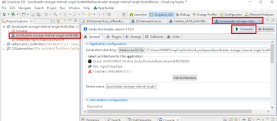
6. Generate and build Gecko bootloader in Simplicity Studio.


7. Now, you can download generated bootloader hex file into your BRD4308A.


Tuesday, December 22, 2020

How to create a delay event in Simplicity Studio v5 and EmberZnet 6.9.0.0

You can use the following steps to create a delay event in Simplicity Studio v5 and EmberZnet 6.9.0.0 when press PB0 on BRD4001A to trigger a delay event.

1. New eventYKDelay as Command and eventYKDelayHandler as Callback in Event Configuration of Includes tab in isc file to generate related codes.

2. Add the following code in button-interface.c

EmberEventControl eventYKDelay;

void eventYKDelayHandler(void){
  emberEventControlSetInactive(eventYKDelay);
  emberSerialPrintfLine(APP_SERIAL, "2000ms delay event");
}

3. Add the the following line in emberAfPluginButtonInterfaceButton0PressedEventHandler to trigger eventYKDelayHandler after 2000 ms.

emberEventControlSetDelayMS(eventYKDelay, 2000);

4. Build and download code into EFR32 radio board.

5. Run the application and press PB0. You will see "2000ms delay event" printed on console 2 seconds later, which shows delay event works.


Monday, December 21, 2020

Create IAS CIE coordinator and IAS Zone Door Sensor using Silicon Labs EmberZnet

The following steps show you how to create IAS CIE coordinator and IAS Zone Door Sensor using Silicon Labs EmberZnet 6.9.0 

1. Create and run IAS CIE coordinator for BRD4180A.

    1.1 Using the following steps to create CIE project for BRD4180A.

    1.2 Select "HA IAS Control and Indication Equipment" as ZCL device type, "Coordinator or Router" as Zigbee Device type, and enable  IAS Zone Client/Network Creator related plugin.


    1.3 Generate code to build firmware and download firmware into BRD4180A.

    1.4 Launch console and use CLI command "plugin network-creator form 1 0x5678 13 13" to form centralized Zigbee 3.0 network.

    1.5 Use CLI command "plugin network-creator-security open-network" to allow IAS Zone device to join.


2. Create and run IAS Zone Door Sensor device for BRD4161A.

    2.1 Using the following steps to create IAS Zone project for BRD4161A.

    2.2 Select "HA IAS Zone" as ZCL device type, "Sleepy End Device" as Zigbee Device type, use 0x0015 as zone type, enable "Security Sensor Interface" and "Network Creator..." related plugin.


    2.3 Add the following pin defines in hal-config.h to simulate PB1 on BRD4001A as reed switch of door sensor.

            #define GPIO_SENSOR_PIN                       (7U)
            #define GPIO_SENSOR_PORT                      (gpioPortF)

    2.4  Generate code to build firmware and download firmware into BRD4161A.

    2.5 Launch console and use CLI command "plugin network-steering start 0" to join centralized Zigbee 3.0 network that is formed and opened in step 1.4 and 1.5.


    2.5 In sniffer log, you would see the following event that show you IAS Zone sensor works with CIE. Press PB1 on BRD4001A would send IAS Zone status change notification.


Friday, September 4, 2020

Build an OpenThread Sleepy End Device Doorlock Prototype using Simplicity Studio v5 and EFR32XG21

The following steps show you how to build an OpenThread Sleepy End Device Doorlock Prototype using Simplicity Studio v5 and EFR32XG21

1. Start Simplicity Studio v5 and connect EFR32XG21 BRD4180A. Form Launcher tab, select sleepy-demo-mtd to create the project.


2. In Simplicity IDE tab, open sleepy-demo-mtd.slcp and click "FORCE GENERATION" button to generate related codes.


3. Change related network settings in setNetworkConfiguration function (main.c) so the device can join matched OpenThread Border Router network (refer to here to setup OpenThread Border Router).


4. Implement handleNetifStateChanged and call "otSetStateChangedCallback(instance, handleNetifStateChanged, instance);" after setNetworkConfiguration to setup sleepy end device doing polling.

void handleNetifStateChanged(uint32_t aFlags, void *aContext)
{
    otLinkModeConfig config;

    if ((aFlags & OT_CHANGED_THREAD_ROLE) != 0)
    {
        otDeviceRole changedRole = otThreadGetDeviceRole(aContext);

        switch (changedRole)
        {
        case OT_DEVICE_ROLE_LEADER:
        case OT_DEVICE_ROLE_ROUTER:
            break;

        case OT_DEVICE_ROLE_CHILD:
            config.mRxOnWhenIdle       = 0;
            config.mSecureDataRequests = true;
            config.mDeviceType         = 0;
            config.mNetworkData        = 0;
            otThreadSetLinkMode(instance, config);
            sAllowSleep = true;
            break;

        case OT_DEVICE_ROLE_DETACHED:
        case OT_DEVICE_ROLE_DISABLED:
            break;
        }
    }
}


5. Create coap server with resource URI "ddl/state".

5.1 Add the following includes, defines and global variables in main.c

#include <openthread/coap.h>
#include "utils/code_utils.h"

#define DDL_STATE_URI     "ddl/state"
#define DDL_STATE_LOCK    "lock"
#define DDL_STATE_UNLOCK  "unlock"
otCoapResource mResource_DDL_STATE;
const char mDDLStateUriPath[]=DDL_STATE_URI;
static uint8_t ddlState[15] = DDL_STATE_UNLOCK;

5.2 Add the following coap handler function ddl_state_coapHandler.

static void ddl_state_coapHandler(void *aContext, otMessage *aMessage,
                             const otMessageInfo *aMessageInfo)
{
    otError error = OT_ERROR_NONE;
    otMessage *responseMessage;
    otCoapCode responseCode = OT_COAP_CODE_CHANGED;
    otCoapCode messageCode = otCoapMessageGetCode(aMessage);
    otCoapType messageType = otCoapMessageGetType(aMessage);

    responseMessage = otCoapNewMessage((otInstance*)aContext, NULL);
    otEXPECT_ACTION(responseMessage != NULL, error = OT_ERROR_NO_BUFS);

    otCoapMessageInitResponse(responseMessage, aMessage, OT_COAP_TYPE_ACKNOWLEDGMENT, responseCode);
    otCoapMessageSetToken(responseMessage, otCoapMessageGetToken(aMessage),
                         otCoapMessageGetTokenLength(aMessage));
    otCoapMessageSetPayloadMarker(responseMessage);

    if(OT_COAP_CODE_GET == messageCode)
    {
        error = otMessageAppend(responseMessage, ddlState,
                                strlen((const char*)ddlState));
        otEXPECT(OT_ERROR_NONE == error);

        error = otCoapSendResponse((otInstance*)aContext, responseMessage,
                                   aMessageInfo);
        otEXPECT(OT_ERROR_NONE == error);
    }
    else if(OT_COAP_CODE_POST == messageCode)
    {
        char data[32];
        uint16_t offset = otMessageGetOffset(aMessage);
        uint16_t read = otMessageRead(aMessage, offset, data, sizeof(data) - 1);
        data[read] = '\0';

        /* process message */
        if(strcmp(DDL_STATE_LOCK, data) == 0)
        {
            /* update the attribute state */
            strcpy((char *)ddlState, DDL_STATE_LOCK);
        }
        else if(strcmp(DDL_STATE_UNLOCK, data) == 0)
        {
            /* update the attribute state */
            strcpy((char *)ddlState, DDL_STATE_UNLOCK);
        }
        else
        {
            /* no valid body, fail without response */
            otEXPECT_ACTION(false, error = OT_ERROR_NO_BUFS);
        }

        if (OT_COAP_TYPE_CONFIRMABLE == messageType)
        {
            error = otMessageAppend(responseMessage, ddlState,
                                    strlen((const char*)ddlState));
            otEXPECT(OT_ERROR_NONE == error);

            error = otCoapSendResponse((otInstance*)aContext,
                                       responseMessage, aMessageInfo);
            otEXPECT(OT_ERROR_NONE == error);
        }
    }

exit:

    if (error != OT_ERROR_NONE && responseMessage != NULL)
    {
        otMessageFree(responseMessage);
    }
}

5.3 Add the following code to start coap service and resource right after calling "otThreadSetEnabled(instance, true);" in main function.

    otCoapStart(instance,OT_DEFAULT_COAP_PORT);
    mResource_DDL_STATE.mUriPath = mDDLStateUriPath;
    mResource_DDL_STATE.mContext = instance;
    mResource_DDL_STATE.mHandler = &ddl_state_coapHandler;
    strncpy(mDDLStateUriPath, DDL_STATE_URI, sizeof(DDL_STATE_URI));
    otCoapAddResource(instance,&mResource_DDL_STATE);


6. Add the capability to output IPv6 addree of Sleepy End Device.

6.1 Add the following two global variables in main.c

char str[256];
int str_idx;

6.2 Add the following funtions in main.c

inline uint16_t Swap16(uint16_t v)
{
    return (((v & 0x00ffU) << 8) & 0xff00) | (((v & 0xff00U) >> 8) & 0x00ff);
}

inline uint16_t HostSwap16(uint16_t v)
{
    return Swap16(v);
}

void printIPv6Addr(void)
{
  const otNetifAddress *unicastAddrs;

  str_idx=0;
  memset(str,0x0,256);
  sprintf(str,"OpenThread Doorlock COAP Demo\r\nipaddr\r\n");
  str_idx=strlen(str);
  unicastAddrs = otIp6GetUnicastAddresses(instance);
  const otNetifAddress *addr = unicastAddrs;
  for (; addr; addr = addr->mNext){
      str_idx=strlen(str);
      sprintf(&str[str_idx],"%x:%x:%x:%x:%x:%x:%x:%x\r\n",
              HostSwap16(addr->mAddress.mFields.m16[0]), HostSwap16(addr->mAddress.mFields.m16[1]),
              HostSwap16(addr->mAddress.mFields.m16[2]), HostSwap16(addr->mAddress.mFields.m16[3]), HostSwap16(addr->mAddress.mFields.m16[4]),
              HostSwap16(addr->mAddress.mFields.m16[5]), HostSwap16(addr->mAddress.mFields.m16[6]), HostSwap16(addr->mAddress.mFields.m16[7])
             );
  }
  otPlatUartSend(str,sizeof(str));
}


6.3 Add calling printIPv6Addr in sl_button_on_change to print IPv6 address when button 1 is pressed.


7. Build and download sleepy-demo-mtd.hex into your EFR32XG21 BRD4180A.


8. Reset EFR32XG21 BRD4180A to join OpenThread Border Router and press PB1 on BRD4001A to output IPv6 address of Sleepy End Device.


9. Now, you can use libcoap to get and set doorlock state through coap server running on EFR32XG21 BRD4180A Sleepy End Device.


P.S. You can use Simplicity Studio Energy Profiler to check power consumption of Sleepy End Device and make sure it goes to sleep mode when not doing polling.