Showing posts with label Raspberry Pi. Show all posts

Tuesday, July 26, 2022

How to build EmberZnet 7.1.0.0 Z3Gateway on Raspberry Pi.

 The following steps show you how to build EmberZnet 7.1.0.0 Z3Gateway on Raspberry Pi.


1. Install Simplicity Studio v5 and GSDK 4.1.0 on Ubuntu 20.04LTS. For example, GSDK 4.1.0 is installed at "~/SimplicityStudio/SDKs/gecko_sdk_2" in my test.

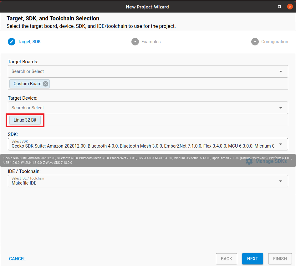
2. Start Simplicity Studio File->New->Silicon Labs Project Wizard... and set "Target Device" as "Linux 32 Bit" to click NEXT button.


3. Select "Zigbee - Host Gateway" and click NEXT button.


4. Make sure you set project location to under your GSDK 4.1.0 folder such as my example "/home/yk/SimplicityStudio/SDKs/gecko_sdk_2/Z3Gateway" and select "Copy contents" to click FINISH button.


5. Download and setup 2022-04-04-raspios-bullseye-armhf-lite.img for your Raspberry Pi.

6. Use sftp to copy the whole "/home/yk/SimplicityStudio" folder contents to your Raspberry Pi home folder.

7. Change direct to "~/SimplicityStudio/SDKs/gecko_sdk_2/Z3Gateway" on your Raspberry Pi and run "make -f Z3Gateway.Makefile" to build Z3Gateway

8. After build successfully, you will get Z3Gateway binary under "~/SimplicityStudio/SDKs/gecko_sdk_2/Z3Gatewaybuild/debug/". You can run Z3Gateway by "Z3Gateway -p /dev/ttyACM0" under this folder.


Thursday, July 1, 2021

How to build OpenThread Sleepy MTD CoAP temperature sensor using Simplicity Studio v5 and BRD4161A

The following steps show you how to build an OpenThread Sleepy MTD CoAP temperature sensor using Simplicity Studio v5 and BRD4161A

1. Start Simplicity Studio v5 and connect EFR32MG12 BRD4161A. Form Launcher tab, select sleepy-demo-mtd (I use OpenThread SDK 1.2.0.0 when I test this) to create the project.


2.  We will add temperature reading (from Si7021) related codes in this step.

2.1 In Simplicity IDE tab, open sleepy-demo-mtd.slcp to make sure you enable "Relative Humidity and Temperature sensor" and set proper I2C pins.


2.2 You also need to check sl_board_control_config.h and make sure SL_BOARD_ENABLE_SENSOR_RHT is defined as "1" and SL_BOARD_ENABLE_SENSOR_RHT_PORT/SL_BOARD_ENABLE_SENSOR_RHT_PIN are defined to correct port/pin which is PB10 on BRD4161A. 

2.3 Set "sl_i2cspm_t *i2cspm_sensor = sl_i2cspm_inst0;" in sl_sensor_select.c.

2.4 Create periodic event to read temperature from humidity/temperature sensor Si7021.

2.4.1 Add the following header files for humidity/temperature reading and timer event.

#include "sl_i2cspm_instances.h"
#include "sl_si70xx.h"
#include "sl_sleeptimer.h"
#include <stdio.h>
#include <string.h>


2.4.2 Add the following lines in app_init in app.c to initialize Si7021 humidity/temperature sensor.

    otCliOutputFormat("app_init: sl_si70xx_init\r\n");
    sl_si70xx_init(sl_i2cspm_inst0, SI7021_ADDR);


 2.4.3 Add timer related defines/variables/callback function and add timer start in app_init in app.c.

#define MEASUREMENT_INTERVAL_MS      5000
static sl_sleeptimer_timer_handle_t measurement_timer;


static void measurement_callback(sl_sleeptimer_timer_handle_t *handle, void *data)
{
  otCliOutputFormat("measurement_callback\r\n");
  sl_si70xx_measure_rh_and_temp(sl_i2cspm_inst0, SI7021_ADDR, &rh_data, &temp_data);
  memset(str_buf,0,64);
  sprintf(str_buf,"rh=%f, temperature=%f\r\n",((float)rh_data/1000.0),((float)temp_data/1000.0));
  otCliOutputFormat(str_buf);
}


void app_init(void)
{
... 
otCliOutputFormat("app_init: Setup periodic measurement timer \r\n");
sl_sleeptimer_start_periodic_timer_ms(&measurement_timer, MEASUREMENT_INTERVAL_MS, measurement_callback, NULL, 0, 0);
...
}


3.  Change related network settings in setNetworkConfiguration function (in sleepy-mtd.c) so the device can join matched OpenThread Border Router network (refer to here to setup OpenThread Border Router).


4. Implement CoAP related codes.

4.1 Add the following header files in app.c

#include <openthread/coap.h>
#include "utils/code_utils.h"


 4.2 Add CoAP related defines and variables.

#define TEMPERATURE_STATE_URI     "temp/celcius"
otCoapResource mResource_TEMPERATURE_STATE;
const char mTEMPERATUREStateUriPath[]=TEMPERATURE_STATE_URI;

4.3 Implement CoAP processing callback

static void temperature_state_coapHandler(void *aContext, otMessage *aMessage,
                             const otMessageInfo *aMessageInfo)
{
    otCliOutputFormat("sleepy-demo-mtd temperature_state_coapHandler\r\n");
    otError error = OT_ERROR_NONE;
    otMessage *responseMessage;
    otCoapCode responseCode = OT_COAP_CODE_CHANGED;
    otCoapCode messageCode = otCoapMessageGetCode(aMessage);
    otCoapType messageType = otCoapMessageGetType(aMessage);

    responseMessage = otCoapNewMessage((otInstance*)aContext, NULL);
    otEXPECT_ACTION(responseMessage != NULL, error = OT_ERROR_NO_BUFS);

    otCoapMessageInitResponse(responseMessage, aMessage, OT_COAP_TYPE_ACKNOWLEDGMENT, responseCode);
    otCoapMessageSetToken(responseMessage, otCoapMessageGetToken(aMessage),
                         otCoapMessageGetTokenLength(aMessage));
    otCoapMessageSetPayloadMarker(responseMessage);

    if(OT_COAP_CODE_GET == messageCode)
    {
        memset(str_buf,0,64);
        sprintf(str_buf,"%f",((float)temp_data/1000.0));
         otCliOutputFormat("\r\nsleepy-demo-mtd coap get\r\n");
        otCliOutputFormat(str_buf);
        error = otMessageAppend(responseMessage, str_buf,
                                strlen((const char*)str_buf));
        otEXPECT(OT_ERROR_NONE == error);

        error = otCoapSendResponse((otInstance*)aContext, responseMessage,
                                   aMessageInfo);
        otEXPECT(OT_ERROR_NONE == error);
    }

exit:

    if (error != OT_ERROR_NONE && responseMessage != NULL)
    {
        otMessageFree(responseMessage);
    }
}


 4.4 Add CoAP start codes in app_init.

otCoapStart(otGetInstance(),OT_DEFAULT_COAP_PORT);

mResource_TEMPERATURE_STATE.mUriPath = mTEMPERATUREStateUriPath;    

mResource_TEMPERATURE_STATE.mContext = otGetInstance(); 

mResource_TEMPERATURE_STATE.mHandler = &temperature_state_coapHandler;

strncpy(mTEMPERATUREStateUriPath, TEMPERATURE_STATE_URI, sizeof(TEMPERATURE_STATE_URI));

otCoapAddResource(otGetInstance(),&mResource_TEMPERATURE_STATE);


 5. Build and download sleepy-demo-mtd.hex into your BRD4161A.


6.Reset BRD4161A to join OpenThread Border Router and use CLI command "ipaddr" to output IPv6 address of Sleepy End Device. 


7.Now, you can run coap-client (install libCoAP) on Raspberry Pi OTBR to get temperature reading through CoAP server running on BRD4161A Sleepy End Device.



Wednesday, February 24, 2021

Project Connected Home over IP (ProjectCHIP) demonstration with EFR32 as ProjectCHIP node, Raspberry Pi as OTBR, and Ubuntu VM as chip-tool

 The follow steps show you how to setup Project Connected Home over IP (ProjectCHIP) demonstration with EFR32 as ProjectCHIP node, Raspberry Pi as OTBR, and Ubuntu VM as chip-tool like in the diagram.


1. Install VirtualBox and Ubuntu 20.04 on your Desktop. Remember select "Bridged Adapter" in your network settings of VirtualBox/Ubuntu.

2. Setup environment (run the following commands in Ubuntu terminal) for building CHIP examples on Ubuntu VM.

    2.1 sudo apt-get install git gcc g++ python pkg-config libssl-dev libdbus-1-dev libglib2.0-dev libavahi-client-dev ninja-build python3-venv python3-dev unzip

    2.2.1 cd ~
    2.2.2 git clone https://github.com/SiliconLabs/sdk_support.git
    2.2.3 cd sdk_support
    2.2.4 git checkout ff45be117a5a1a20d27296628b0632523f65c66a

    2.3.1 cd ~
    2.3.2 git clone https://github.com/project-chip/connectedhomeip.git
    2.3.3 cd connectedhomeip
    2.3.4 git checkout 122da92801fd38f49b8fe3db397ccaa4eb0e4798
    2.3.5 source scripts/activate.sh
    2.3.6 gn gen out/host
    2.3.7 ninja -C out/host

3. Build and download CHIP lock-app for EFR32 (In my examples, I use BRD4180A with BRD4001A to act as Thread node running CHIP protocol)

    3.1 cd ~/connectedhomeip/examples/lock-app/efr32
    3.2 git submodule update --init
    3.3 source third_party/connectedhomeip/scripts/activate.sh
    3.4 export EFR32_SDK_ROOT=~/sdk_support
    3.5 export EFR32_BOARD=BRD4180A
    3.6 gn gen out/debug --args="efr32_sdk_root=\"${EFR32_SDK_ROOT}\" efr32_board=\"${EFR32_BOARD}\""
    3.7 ninja -C out/debug
    3.8 Using Simplicity Studio Commander to download chip-efr32-lock-example.s37 under out/debug folder into BRD4180A.

4. Refer to "Running OpenThread Border Router and device with Raspberry Pi and Silicon Labs EFR32 Kits" to setup OpenThread Border Router on Raspberry Pi.

5. Run the following commands in OpenThread Border Router terminal to setup Thread network for commission.

    5.1.1 sudo ot-ctl dataset init new
    5.1.2 sudo ot-ctl dataset channel 13
    5.1.3 sudo ot-ctl dataset panid 0xface
    5.1.4 sudo ot-ctl dataset extpanid face1111face2222
    5.1.5 sudo ot-ctl dataset networkname OpenThreadYKTest
    5.1.6 sudo ot-ctl dataset masterkey 00112233445566778899aabbccddeeff
    5.1.7 sudo ot-ctl dataset commit active

    5.2.1 sudo ot-ctl prefix add 2001:db8::/64 pasor
    5.2.2 sudo ot-ctl ifconfig up
    5.2.3 sudo ot-ctl thread start
    5.2.4 sudo ot-ctl netdata register
    5.2.5 sudo ot-ctl state
    5.2.6 sudo ot-ctl ipaddr


    5.3.1 sudo ip addr add dev eth0 2002::2/64

 
6. Run the following commands on terminal of EFR32 CHIP lock-app device (build and download in step 3)

    6.1 factoryreset
    6.2 dataset channel 13
    6.3 dataset panid 0xface
    6.4 dataset masterkey 00112233445566778899aabbccddeeff
    6.5 dataset commit active
    6.6 ifconfig up
    6.7 thread start
    6.8 ipaddr

7. Try to ping EFR32 CHIP lock-app device from Raspberry Pi border router to make sure it respond.


8. Add route (enp0s3 might be different on your VM) on Ubuntu VM to access to EFR32 CHIP lock-app device

    8.1 sudo ifconfig enp0s3 inet6 add 2002::1/64
    8.2 sudo ip route add 2001:db8:0:0::/64 via 2002::2
    8.3 sudo ip route add fd38:117c:3b66::/64 via 2002::2


     8.4Try to ping EFR32 CHIP lock-app device from Ununtu VM terminal this time to make sure it respond.


9. Build and run chip-tool on Ubuntu VM

    9.1 cd ~/connectedhomeip/examples/chip-tool
    9.2 git submodule update --init
    9.3 source third_party/connectedhomeip/scripts/activate.sh
    9.4 gn gen out/debug
    9.5 ninja -C out/debug

    9.6 run "./chip-tool onoff on 2001:DB8::C6CC:14E9:E7D1:A3EA 11097 1" to send onoff command on Ubuntu VM terminal to control EFR32 CHIP lock-app device


    9.7 Using J-link RTT Viewer to check if EFR32 CHIP lock-app device receives CHIP command.


P.S. This demostartion is based on steps in https://www.silabs.com/documents/public/training/wireless/chip-connected-home-over-ip-lab.pdf. However, there are some typo and ambiguous in the document and here I share the whole steps again according to my test.

Tuesday, August 25, 2020

Build OpenThread Sleepy End Device doorlock prototype to test with Rasperry Pi OpenThread Border Router

The following steps show how to build OpenThread Sleepy End Device doorlock prototype to test with Rasperry Pi OpenThread Border Router

1. Build OpenThread Sleepy End Device doorlock prototype for TI LAUNCHXL-CC26X2R1

1.1 Download/Install TI CCS 10.1 and SIMPLELINK-CC13X2-26X2-SDK v4.20.00.35.

1.2 Import thread door_lock example from C:\ti\simplelink_cc13x2_26x2_sdk_4_20_00_35\examples\rtos\CC26X2R1_LAUNCHXL\thread\door_lock

1.3 Set door_lock as Sleepy End Device from sysconfig.


1.4 Add the following codes in tiop_ui.c for providing API to output IPv6 address to UART console.

inline uint16_t Swap16(uint16_t v)
{
    return (((v & 0x00ffU) << 8) & 0xff00) | (((v & 0xff00U) >> 8) & 0x00ff);
}
 

inline uint16_t HostSwap16(uint16_t v)
{
    return Swap16(v);
}

void tiopCUIOutputIp6Address(otIp6Address aAddress)
{
    CUI_statusLinePrintf(
        clientHandle, nwkInfoLine1,
        "[" CUI_COLOR_GREEN "IPv6" CUI_COLOR_RESET "] %s - %x:%x:%x:%x:%x:%x:%x:%x",
        "Addr",
        HostSwap16(aAddress.mFields.m16[0]), HostSwap16(aAddress.mFields.m16[1]),
                HostSwap16(aAddress.mFields.m16[2]), HostSwap16(aAddress.mFields.m16[3]), HostSwap16(aAddress.mFields.m16[4]),
                HostSwap16(aAddress.mFields.m16[5]), HostSwap16(aAddress.mFields.m16[6]), HostSwap16(aAddress.mFields.m16[7]));
}

1.5 Add the following line to expose API tiopCUIOutputIp6Address in tiop_ui.h.

extern void tiopCUIOutputIp6Address(otIp6Address aAddress);

1.6 Add the following line in "case DoorLock_evtKeyRight:..." of processEvent (doorlock.c) to output IPv6 address when right button is pressed.

tiopCUIOutputIp6Address(*(otThreadGetRloc(OtInstance_get())));

1.7 Build and download sleepy door_lock firmware into LAUNCHXL-CC26X2R1.


2. Setup OpenThread Border Router and libcoap on Raspberry Pi.

2.1 Refer to this link to setup OpenThread Border Router on Raspberry Pi.

2.2 Run the following command in Raspberry Pi console to setup libcoap.

      sudo apt install autoconf automake libtool
      git clone --depth 1 --recursive -b dtls https://github.com/home-assistant/libcoap.git
      cd libcoap
      ./autogen.sh
      ./configure --disable-documentation --disable-shared --without-debug CFLAGS="-D COAP_DEBUG_FD=stderr"
      make
      sudo make install

3. Use the following commands on Raspberry Pi console and start sleepy door_lock to join thread network. Then, press right button on LAUNCHXL-CC26X2R1 to print IPv6 address of sleepy door_lock.

sudo ot-ctl commissioner start
sudo ot-ctl commissioner joiner add 00124b001ca16238 DRRLCK1

4. Use the following command to request lock state of sleepy door_lock from border router.

coap-client -m get coap://[fd11:1111:1122:0:0:ff:fe00:ec08]/doorlock/lockstate

5. Use the following command to change lock state of sleepy door_lock from border router.

coap-client -m post coap://[fd11:1111:1122:0:0:ff:fe00:ec08]/doorlock/lockstate -e unlock


Wednesday, April 29, 2020

How to run node server with EmberZnet 6.7.3 Z3GatewayHost on Raspberry Pi.

Although Silicon Labs deprecates UG129: zigbee® Gateway Reference Design User's Guide, the following steps show you how to run node server with EmberZnet 6.7.3 Z3GatewayHost on Raspberry Pi.

1. Install the Raspbian Jessie Lite operating system on the SD card and start Raspberry Pi to ssh login.

2. Run the following command on console to install node server.

sudo chmod 666 /etc/apt/sources.list
sudo echo deb http://devtools.silabs.com/solutions/apt jessie main >> /etc/apt/sources.list
sudo apt-key adv --keyserver keyserver.ubuntu.com --recv-keys 90CE4F77
sudo apt-get update
sudo apt-get -y install silabs-zigbee-gateway
sudo apt-get -y install silabs-networking


3. Do "sudo reboot" to restart Raspberry Pi.

4. Login Raspberry Pi again and run "sudo service siliconlabsgateway stop" to stop siliconlabsgateway service.

5. Upload modified NCP.py and Z3GatewayHost to your Raspberry Pi root folder.

6.
  • Do "cd /opt/siliconlabs/zigbeegateway/tools/ncp-updater/" to switch to original NCP.py folder and make a copy of original NCP.py with "sudo mv ncp.py ncp-ori.py" if you want. 
  • Copy modified from Raspberry Pi root folder to /opt/siliconlabs/zigbeegateway/tools/ncp-updater/ using "sudo cp ~/ncp6.7.3.py ./ncp.py". 
  • Run "sudo chmod 777 ncp.py"
  • Run "sudo python ncp.py scan" and make sure you see the following response.


7.
  • Do "cd /opt/siliconlabs/zigbeegateway/bin" and run "sudo mv siliconlabsgateway siliconlabsgateway-ori" to make a copy of original siliconlabsgateway if you want. 
  • Copy Z3GatewayHost from Raspberry Pi root folder to /opt/siliconlabs/zigbeegateway/bin using "sudo cp ~/Z3GatewayHost ./siliconlabsgateway".
  • Run "sudo chmod 777 siliconlabsgateway" 
8. Run "sudo reboot" to restart Raspberry Pi and you can access to web service of Z3GatewayHost node server later.


9. If you want to build Z3GatewayHost by yourself, remember to enable all MQTT related and cJSON plugin to generate source codes.


Tuesday, April 24, 2018

How to setup Mosquitto on Raspberry Pi and make Contiki/Contiki-NG cc26xx-web-demo do mqtt publish to it.

The following steps show you how to setup Mosquitto on Raspberry Pi and make Contiki/Contiki-NG cc26xx-web-demo do mqtt publish to it.

1. Login to Raspberry Pi and do the following steps to install Mosquitto.
  • 1.1 Run "apt-get update" and "apt-get install mosquitto" to install Mosquitto server.
  • 2.2 Run "apt-get install mosquitto-clients" to install mosquitto_sub and mosquitto_pub.
2. Follow steps in How to configure 6lbr to make it can do ping6 to a CC26xx/CC13xx node from Raspberry Pi running 6lbr to setup 6lbr in bridge router mode.

3. Do "ifconfig" to get br0 IPv6 address. In my case, it's "bbbb::e786:9d85:9446:709".


4. Go to cc26xx-web-demo MQTT/IBM Cloud Config page and set "bbbb::e786:9d85:9446:709" as broker IP.


5. Open another ssh login to Raspberry pi and run "mosquitto_sub -h bbbb::e786:9d85:9446:709 -t iot-2/evt/status/fmt/json" to subscribe to ccx6xx-web-demo publish topic. You should be it receives cc26xx-web-demo published MQTT messages.


p.s. You can also use "mosquitto_pub -h bbbb::e786:9d85:9446:709 -p 1883 -t iot-2/evt/status/fmt/json -m "hello"" to test MQTT message publish from Raspberry Pi terminal.

6. The following steps show you how to toggle red led on LAUNCHXL-CC1310 or LAUNCHXL-CC2560 running cc26xx-web-demo.
  •  Use "test" as Org ID instead of "quickstart" and "123456" as Auth Token instead of empty.
  • Click "Submit" to make cc26xx-web-demo to reconnect to mqtt server.
  • Start a ssh login to raspberry pi. Use "mosquitto_pub -h bbbb::e786:9d85:9446:709 -m "1" -t iot-2/cmd/leds/fmt/json" to turn on red led, or "mosquitto_pub -h bbbb::e786:9d85:9446:709 -m "0" -t iot-2/cmd/leds/fmt/json" to turn off red led.


Monday, April 23, 2018

How to connect Contiki-NG cc26xx-web-demo to IBM Watson IoT Platform.

The following steps show you how to connect Contiki-NG cc26xx-web-demo (running on LAUNCHXL-1310 or LAUNCHXL-CC2650) to IBM Watson IoT Platform.

1. Setup IBM Watson IoT Platform.
  • 1.1 Login to IBM Watson IoT Platform and go to SECURITY tab of Device page to use "TLS Optional". This step is critical. If you don't do this, you need to use TLS for connection and default cc26xx-web-demo won't work.

  • 1.2 Go to Device Types tab of Device page to click "Add Device Type".
  • 1.3 Input device type name. I use cc26xx-web-demo in this demo.
  • 1.4 Follow all the steps to finish add device type.
  • 1.5 Switch to Browse tab of Device page to click "Add Device".
  • 1.6 Select "Select Existing Device Type" to cc26xx-web-demo and input Device ID which I use device MAC address.
  • 1.7 Input authentication token.
  • 1.8 Keep your device credentials carefully.
  • 1.9 Finish adding device and you would see it on Browse tab of device page.

2. Running 6lbr and wrapsix on Raspberry Pi first and connect your cc26xx-web-demo running on LAUNCHXL-CC1310 or LAUNCHXL-CC2650 to your 6lbr and configure cc26xx-web-demo.
  • 2.1 Open "MQTT/IBM Cloud Config" page.
  • 2.2 Configure cc26xx-web-demo for IBM Watson IoT platform according to device credentials in step 1.7.
  • 2.3 Run "ping uc6bmi.messaging.internetofthings.ibmcloud.com" to get its IPv4 address 169.45.2.20.
  • 2.4 Change broker IP to "0064:ff9b:0000:0000:0000:0000:a92d:0214" which is IPv6 address of "169.45.2.20".
  • 2.5 Click "Submit" on "MQTT/IBM Cloud Config" page to connect to IBM Watson IoT platform.