Wednesday, October 4, 2023

DIY SwitchBot using Matter Over Thread running on Silicon Labs EFR32xG24 Explorer Kit in 5 Minutes.

The following steps guide you to DIY SwitchBot using Matter Over Thread running on Silicon Labs EFR32xG24 Explorer Kit xG24-EK2703A in 5 minutes.

1. Make sure you install Silicon Labs Simplicity Studio v5 and GSDK 4.3.1 with Matter extension 2.1.0-1.1.

2.Connect your xG24-EK2703A kit to your desktop and create "Matter - SoC OnOff Plug over Thread" project as base for your DIY SwitchBot using Matter Over Thread project.

3.Install and add a "sg90" PWM instance in "SOFTWARE COMPONENTS"
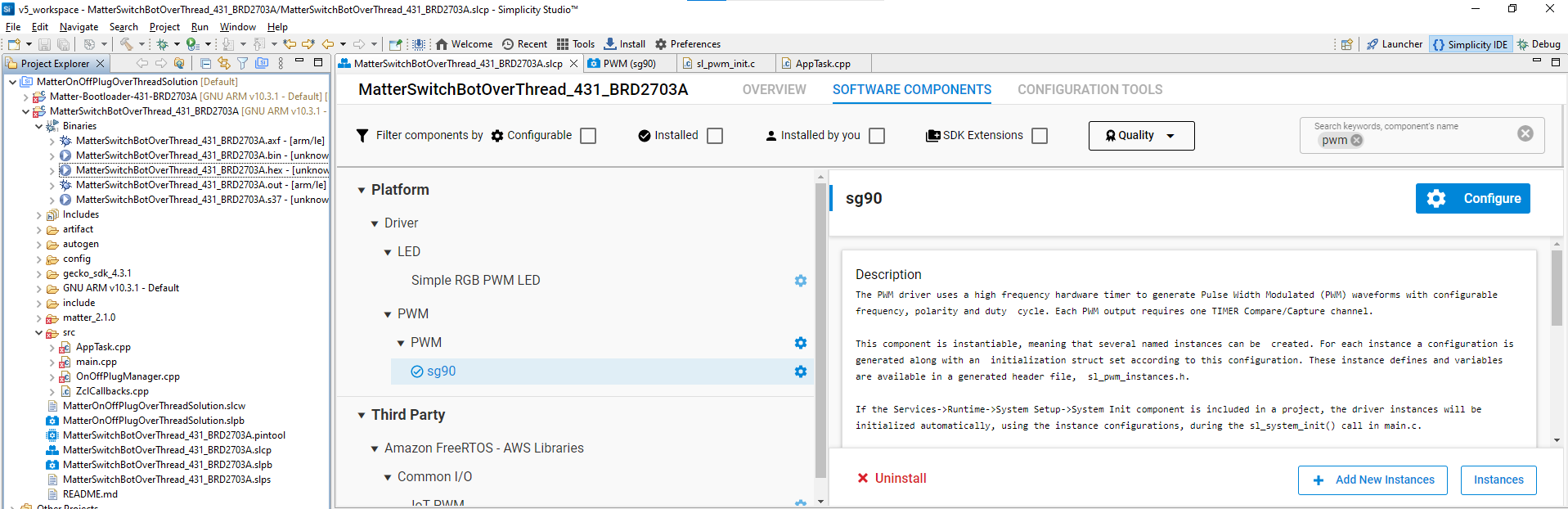
4.Configure "sg90" instance to use Timer0 PA00 as PWM output with PWM frequency 50 Hz.


5. Replace source code in "void AppTask::ActionCompleted(OnOffPlugManager::Action_t aAction)" with the following codes (red lines), which implements on/off rotating position for SG90 to turn on/off switch.

//YK for SG90 SwitchBot
#include "sl_pwm.h"
#include "sl_pwm_init_sg90_config.h"
#include "sl_sleeptimer.h"

extern sl_pwm_instance_t sl_pwm_sg90;

void AppTask::ActionCompleted(OnOffPlugManager::Action_t aAction)
{
    // action has been completed on the outlet
    if (aAction == OnOffPlugManager::ON_ACTION)
    {
        SILABS_LOG("Outlet ON")
        sl_pwm_set_duty_cycle(&sl_pwm_sg90, 2);
        sl_pwm_start(&sl_pwm_sg90);
        sl_sleeptimer_delay_millisecond(200);
        sl_pwm_set_duty_cycle(&sl_pwm_sg90, 5);
        sl_sleeptimer_delay_millisecond(200);
        sl_pwm_stop(&sl_pwm_sg90);
    }
    else if (aAction == OnOffPlugManager::OFF_ACTION)
    {
        SILABS_LOG("Outlet OFF")
        sl_pwm_set_duty_cycle(&sl_pwm_sg90, 9);
        sl_pwm_start(&sl_pwm_sg90);
        sl_sleeptimer_delay_millisecond(200);
        sl_pwm_set_duty_cycle(&sl_pwm_sg90, 5);
        sl_sleeptimer_delay_millisecond(200);
        sl_pwm_stop(&sl_pwm_sg90);
    }
#ifdef SL_CATALOG_SIMPLE_BUTTON_PRESENT
    if (sAppTask.mSyncClusterToButtonAction)
    {
        chip::DeviceLayer::PlatformMgr().ScheduleWork(UpdateClusterState, reinterpret_cast<intptr_t>(nullptr));
        sAppTask.mSyncClusterToButtonAction = false;
    }
#endif
}

6. Add the following two line to set initial SG90 position after "sl_pwm_init(&sl_pwm_sg90, &pwm_sg90_config);" in "void sl_pwm_init_instances(void)".

  //YK for SG90 SwitchBot
  sl_pwm_set_duty_cycle(&sl_pwm_sg90, 5);
  sl_pwm_start(&sl_pwm_sg90);

7. Build and download firmware into xG24-EK2703A kit(remember to dowload bootloader into the kit too)

8. Connect GND, PWR, Signal line of SG90 to GND, 3V3, and PWM pin on xG24-EK2703A kit.

9.Start RTT viewer to get QR code link for Matter Provision.


10. Since Apple Home supports Matter Over Thread now, we use Apple HomePod mini (iOS 17) and iPhone Home App to add our DIY SwitchBot into Apple Home.

11. Now, we can mount the DIY SwitchBot to wall switch and use Apple Home to control wall switch/light remotely.


Thursday, September 7, 2023

Adding reporting period configuration in configuration command class to Z-Wave Multilevel sensor example running on BRD2603A/ZGM230S

The following steps and codes show you how to add a reporting period configuration with configuration command class to allow changing auto report period in Z-Wave Multilevel sensor example running on BRD2603A/ZGM230S

1. Create zwave_soc_multilevel_sensor in Simplicity Studio v5 with GSDK4.3.1/Z-Wave SDK 7.20.1.0.

2. Add 3rd parameter to "configurations:" section in MultilevelSensor.cc_config and SSv5 would rebuilt parameters in parameter_pool inside cc_configuration_config.c accordingly

    - name: "auto report period"
      number: 3
      file_id: 2
      info: "sensor auto reporting period"
      size: CC_CONFIG_PARAMETER_SIZE_32_BIT
      format: CC_CONFIG_PARAMETER_FORMAT_SIGNED_INTEGER
      min_value: 1
      max_value: 3600
      default_value: 1800
      altering_capabilities: 0
      read_only: 0
      advanced: 0

3. In CC_MultilevelSensor_Support.c, revise the following codes:

#define DEBUGPRINT
#include "DebugPrint.h"
#include "CC_Configuration.h"

SSwTimer cc_multilevel_sensor_autoreport_timer;
uint32_t autoreport_time = 30;

static void cc_multilevel_sensor_init(void)
{
  cc_multilevel_sensor_config_register_instances();
  cc_multilevel_sensor_init_all_sensor();
  ZAF_nvm_read(2, &autoreport_time, 4);
  DPRINTF("configuration_pool_init[2].parameters->attributes.default_value %d\r\n", (int)autoreport_time );

  AppTimerDeepSleepPersistentRegister(&cc_multilevel_sensor_autoreport_timer, false, cc_multilevel_sensor_autoreport_callback);
  AppTimerDeepSleepPersistentStart(&cc_multilevel_sensor_autoreport_timer, autoreport_time*1000);
}

static void cc_multilevel_sensor_autoreport_callback(SSwTimer *pTimer)
{
  UNUSED(pTimer);
  cc_multilevel_sensor_send_sensor_data();
  AppTimerDeepSleepPersistentStart(&cc_multilevel_sensor_autoreport_timer, autoreport_time*1000);
}

4. In CC_Configuration.c, add the following red lines into cc_configuration_set.

#include "SwTimer.h"
extern SSwTimer cc_multilevel_sensor_autoreport_timer;
extern uint32_t autoreport_time;
static cc_config_configuration_set_return_value
cc_configuration_set(uint16_t parameter_number,  cc_config_parameter_value_t* new_value, cc_config_parameter_size_t size)
{
  cc_config_configuration_set_return_value return_value = CC_CONFIG_RETURN_CODE_OK;
  bool io_transaction_result = false;
  bool is_value_in_range = false;
  bool has_to_break = false;
  cc_config_parameter_buffer_t parameter_buffer;

  if (parameter_number==3){
    autoreport_time = new_value->as_uint32;
    ZAF_nvm_write(2, &autoreport_time, 4);
    DPRINTF("cc_configuration_set para no. %d size %d: autoreport_time %d seconds\r\n", (int)parameter_number, (int)size, (int)autoreport_time );
    AppTimerDeepSleepPersistentStart(&cc_multilevel_sensor_autoreport_timer);
    AppTimerDeepSleepPersistentStart(&cc_multilevel_sensor_autoreport_timer, autoreport_time*1000);
  }

    for(uint16_t parameter_ix = 0 ; parameter_ix < configuration_pool->numberOfParameters ; parameter_ix++)
    {
...

}

5. Build and run firmware on BRD2603A to join zwave_soc_multilevel_sensor into PC controller. You can use CONFIGURATION_SET to change auto report period with parameter 3.


Friday, September 1, 2023

Using Z-Wave Multilevel sensor example running on BRD2603A/ZGM230S to read temperature from TMP116 temperature sensor

The following example shows you how to use Z-Wave Multilevel sensor example running on BRD2603A/ZGM230S to read temperature from Texas Instrument TMP116 temperature sensor.

1. Connect Texas Instrument BOOSTXL-BASSENSORS TMP116 TMP V+, GND, and SCL/SDA to pin 20, 1, and 15(PB05)/16(PB05) on EXP-header of BRD2603A.


2. Install Z-Wave Debug and Z-Wave Debug Print in project software component to use  DEBUGPRINT to output data to SSv5 console 1.

3.Add the following code into MultilevelSensor_interface_sensor.c

 #define TMP116_I2C_DEVICE                (sl_i2cspm_sensor) /**< I2C device used to control the Si7021  */
#define TMP116_I2C_BUS_ADDRESS           0x48//TMP116 0x40               /**< I2C bus address                        */

static I2C_TransferReturn_TypeDef TMP116_transaction(uint16_t flag,
                                                     uint8_t *writeCmd,
                                                     size_t writeLen,
                                                     uint8_t *readCmd,
                                                     size_t readLen)
{
  I2C_TransferSeq_TypeDef seq;
  I2C_TransferReturn_TypeDef ret;

  seq.addr = TMP116_I2C_BUS_ADDRESS << 1;
  seq.flags = flag;

  switch (flag) {
    // Send the write command from writeCmd
    case I2C_FLAG_WRITE:
      seq.buf[0].data = writeCmd;
      seq.buf[0].len  = writeLen;

      break;

    // Receive data into readCmd of readLen
    case I2C_FLAG_READ:
      seq.buf[0].data = readCmd;
      seq.buf[0].len  = readLen;

      break;

    // Send the write command from writeCmd
    // and receive data into readCmd of readLen
    case I2C_FLAG_WRITE_READ:
      seq.buf[0].data = writeCmd;
      seq.buf[0].len  = writeLen;

      seq.buf[1].data = readCmd;
      seq.buf[1].len  = readLen;

      break;

    default:
      return i2cTransferUsageFault;
  }

  // Perform the transfer and return status from the transfer
  ret = I2CSPM_Transfer(TMP116_I2C_DEVICE, &seq);

  return ret;
}

uint32_t TMP116_read()
{
  I2C_TransferReturn_TypeDef ret;
  uint8_t temp[2];
  uint8_t cmdReadTemp[1]={0x00};
  int32_t temperature;

  // Wait for sensor to become ready
  //sl_sleeptimer_delay_millisecond(1000);

  // Check for device presence  and compare device ID
  ret = TMP116_transaction(I2C_FLAG_WRITE_READ, cmdReadTemp, 1, temp, 2);
  temperature=temp[0];
  temperature=(temperature<<8)|temp[1];
  //DPRINTF("Temperature = %d\r\n", (int)temperature);
  return temperature*10;
}

4. Replace "MultilevelSensor_temperature_humidity_sensor_read(&rh_data, &temp_data);" with "temp_data=(int32_t)TMP116_read();" in cc_multilevel_sensor_air_temperature_interface_read_value.

5. Build and run the firmware on BRD2603A to see the following temperature reading fromTMP116


P.S. If you use Texas Instrument instead of TMP117, it should work similarly. 


Thursday, August 31, 2023

Using Z-Wave Multilevel sensor example running on BRD2603A/ZGM230S to read temperature from DS18B20 one-wire sensor

The following example shows you how to use Z-Wave 800 Multilevel sensor example running on BRD2603A/ZGM230S to read temperature from DS18B20 one-wire sensor.

1. Connect DS18B20 Vdd, GND, and DQ (add extra 4.7K pull-high to Vdd) to pin 20, 1, and 2(PB03) on EXP-header of BRD2603A.

2. Install USTIMER, Z-Wave Debug, and Z-Wave Debug Print in project software component to use microsecond delay API USTIMER_DelayIntSafe and DEBUGPRINT to output data to SSv5 console 1.

3. Add the following code into MultilevelSensor_interface_sensor.c

#include "em_gpio.h"
#include "ustimer.h" //For microsecond delay
#include "em_core_generic.h" //For critical section

//Use PB03 on BRD2603A
#define DS_GPIO_PORT 1 //gpioPortB
#define DS_GPIO_PIN  3

#define CMD_CONVERTTEMP 0x44
#define CMD_RSCRATCHPAD 0xbe
#define CMD_WSCRATCHPAD 0x4e
#define CMD_CPYSCRATCHPAD 0x48
#define CMD_RECEEPROM 0xb8
#define CMD_RPWRSUPPLY 0xb4
#define CMD_SEARCHROM 0xf0
#define CMD_READROM 0x33
#define CMD_MATCHROM 0x55
#define CMD_SKIPROM 0xcc
#define CMD_ALARMSEARCH 0xec
#define DECIMAL_STEPS_12BIT 625 //.0625

inline void pullLineLow() {
    GPIO_PinModeSet(DS_GPIO_PORT, DS_GPIO_PIN, gpioModePushPull, 0);
}

inline void releaseLine() {
    GPIO_PinModeSet(DS_GPIO_PORT, DS_GPIO_PIN, gpioModeInputPull, 1);
}

inline void delayUs(uint16_t us) {
  USTIMER_DelayIntSafe(us);
}

inline uint32_t readLineState() {
    return GPIO_PinInGet(DS_GPIO_PORT, DS_GPIO_PIN);
}

void writeBit(uint8_t bit){
  //Pull line low for 1uS
  pullLineLow();
  delayUs(1);
  //If we want to write 1, release the line (if not will keep low)
  if(bit) {
        releaseLine();
    }
  //Wait for a while and release the line
  delayUs(20);
  releaseLine();
  delayUs(1);
}

uint8_t readBit(void){
  uint8_t bit = 0;
  //Pull line low for 1uS
  pullLineLow();
  delayUs(1);
  //Release line and wait for a while
  releaseLine();
  delayUs(8);
  //Read line value
  if(readLineState()){
        bit=1;
    }
  //Wait for a while to return read value
  delayUs(40);
  return bit;
}

uint8_t readByte(void){
  uint8_t i = 8, n = 0;
  while(i--){
    //Shift one position right and store read value
    n >>= 1;
    n |= (readBit() << 7);
  }
  return n;
}

void writeByte(uint8_t b){
  uint8_t i = 8;
  while(i--){
    //Write actual bit and shift one position right to make the next bit ready
    writeBit(b & 1);
    b >>= 1;
  }
}

uint32_t reset(){
  uint32_t i;
  pullLineLow();
  delayUs(300);
  releaseLine();
  delayUs(60);
  i = readLineState(); //(0=OK, 1=ERROR)
  delayUs(300);
  return i;
}

/*
    Returns temperature read from DS18B20
    Reading is returned mutiplied by 10000 i.e.
    for 23.4560 degrees the result will be 234560
*/
uint32_t ds18b20GetTemparature(){
  USTIMER_Init();

  //Enter cirtical section
  CORE_DECLARE_IRQ_STATE;
  CORE_ENTER_CRITICAL();

  //Reset, skip ROM and start temperature conversion
  if(reset()) {
      DPRINT("DS18B20 is not responding---reset temperature conversion\n");
        return 0;
    }
  writeByte(CMD_SKIPROM);
  writeByte(CMD_CONVERTTEMP);

  //Wait until conversion is complete
  uint16_t timeout = 0xFFFF;
  while(!readBit() && timeout > 0) {
        timeout--;
        //Feed WDG to avoid WDG reboot.
        zpal_feed_watchdog();
    }
    if(0 == timeout) {
        DPRINT("DS18B20 temperature conversion has timed out\n");
        return 0;
    }

  //Reset, skip ROM and send command to read Scratchpad
  if(reset()) {
      DPRINT("DS18B20 is not responding---reset Scratchpad\n");
        return 0;
    }
  writeByte(CMD_SKIPROM);
  writeByte(CMD_RSCRATCHPAD);

  uint8_t scratchpad[2] = {0, 0};
  //Read Scratchpad (only 2 first bytes)
  scratchpad[0] = readByte();
  scratchpad[1] = readByte();

  //Exit critial section.
  CORE_EXIT_CRITICAL();

  USTIMER_DeInit();

  int8_t digit = scratchpad[0] >> 4;
  digit |= (scratchpad[1] & 0x7) << 4;
  //Store decimal digits
  uint16_t decimal = scratchpad[0] & 0xf;
  decimal *= DECIMAL_STEPS_12BIT;

    return digit * 10000 + decimal;
}

4. Use the following two lines to replace "MultilevelSensor_temperature_humidity_sensor_read(&rh_data, &temp_data);" in cc_multilevel_sensor_air_temperature_interface_read_value.

    temp_data=ds18b20GetTemparature();
    temp_data=(int32_t)(temp_data/10);

5. Build and run the firmware on BRD2603A to see the following temperature reading from DS18B20.